
6 Volt regulator circuit using 7806-Voltage regulator IC
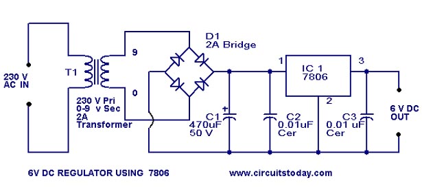
The 7806 voltage regulator is a widely used integrated circuit that provides a stable output voltage of 6 volts with a maximum output current of 1 ampere. This circuit is particularly useful for powering low-voltage electronic devices, ensuring consistent performance regardless of variations in input voltage or load conditions.
The basic configuration of the 7806 regulator circuit includes the following components: the 7806 IC, input and output capacitors, and a heat sink if necessary. The input capacitor, typically a 0.33 µF ceramic capacitor, is connected between the input pin of the 7806 and ground to filter out high-frequency noise from the input voltage source. The output capacitor, usually a 0.1 µF ceramic capacitor, is connected between the output pin and ground to improve transient response and stability of the output voltage.
The input voltage supplied to the 7806 must be higher than 6 volts, typically in the range of 7 to 35 volts, to ensure proper regulation. The maximum input-output voltage differential must not exceed the specified limits of the IC to prevent damage. It is also recommended to include a heat sink on the 7806 if the load current approaches the maximum limit, as this will help dissipate heat generated during operation.
The circuit schematic consists of the 7806 IC with its three pins: input (VIN), output (VOUT), and ground (GND). The input voltage is connected to the VIN pin, while the output voltage can be taken from the VOUT pin. The GND pin is connected to the common ground of the circuit. The input and output capacitors are placed close to the IC pins to minimize lead inductance and enhance stability.
Overall, this simple 6-volt DC regulator circuit is an effective solution for providing a reliable power supply for various electronic applications, ensuring that devices receive the necessary voltage for optimal operation.A simple 6 volt dc regulator circuit with diagram and schematic using 7806 Ic, a positive voltage regulator.Its an elementary 6 volt,1 ampere power supply circuit.. 🔗 External reference
Related Circuits
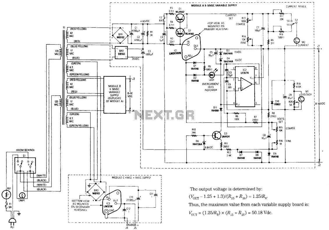
The design's value is derived from the use of IC1, an LM317HVK adjustable series-pass voltage regulator, which provides broad-range performance along with voltage-setting and current-limiting functions. The input to IC1 is sourced from the output of BR1, which is...
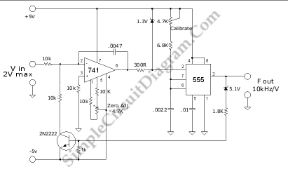
A voltage-to-frequency converter (VFC) circuit is illustrated in the schematic diagram below. The circuit utilizes a 555 integrated circuit (IC) as the central component of its operation. The voltage-to-frequency converter (VFC) is a crucial electronic circuit that converts an input...
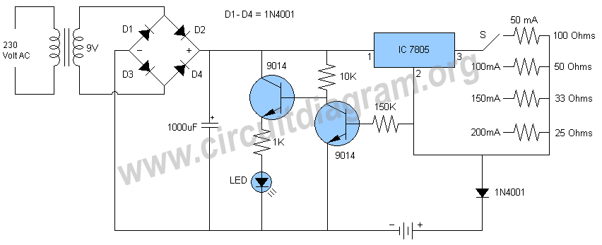
Schematic and description of a simple automatic NiMH battery charger circuit using IC 7805 with multiple selectable current options for charging. The described circuit is a straightforward automatic charger designed for Nickel-Metal Hydride (NiMH) batteries. It utilizes the IC 7805...
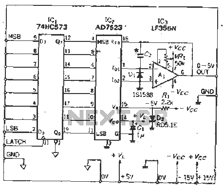
The IC latch is utilized to hold the digital data when the clock signal rises. The configuration includes a holding data port AD7s23, a thin film resistor ladder, and a switch that together form an 8-bit Digital-to-Analog Converter (DAC)....
This page demonstrates how to construct a Geiger-Müller counter, an essential device that not only indicates the presence of radioactive materials but also highlights the associated dangers. The Geiger-Müller counter operates similarly to a photometer, measuring high-energy particle radiation...
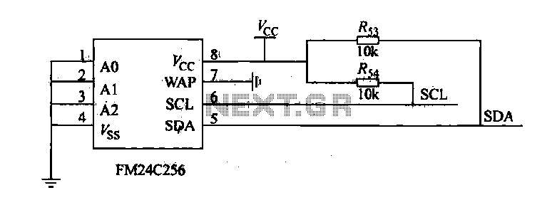
The FM24C256 is utilized as a slave interface circuit in an I2C bus configuration, with the address format specified in Table 27-3. The address pins A2, A1, and A0 are set to low; however, for extended storage capacity, adjustments...