
Voltage-To-Frequency Converter (VFC) with 555 IC
 with 555 IC")
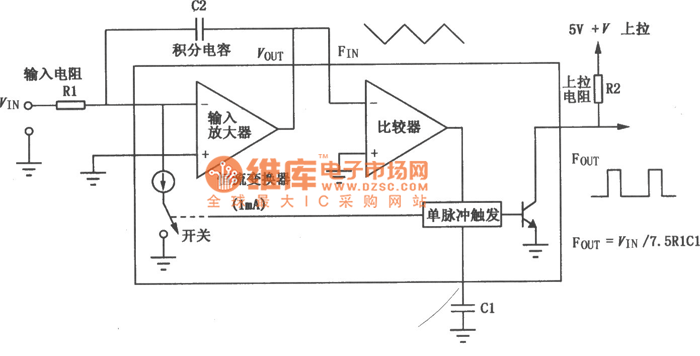
The voltage-to-frequency converter (VFC) is a crucial electronic circuit that converts an input voltage signal into a corresponding frequency output. This conversion process is particularly useful in various applications such as analog-to-digital conversion, signal processing, and frequency modulation.
In this circuit, the 555 timer IC operates in astable mode to generate a square wave output whose frequency is directly proportional to the input voltage. The configuration typically involves resistors and capacitors connected to the 555 timer, which determine the timing intervals and thus the frequency of the output signal.
The input voltage is applied to a control pin of the 555 timer, which adjusts the duty cycle of the output waveform based on the voltage level. The output frequency can be calculated using the formula derived from the 555 timer's timing characteristics, which incorporates the values of the resistors and capacitors in the circuit.
To ensure accurate operation, it is important to select appropriate resistor and capacitor values that suit the desired frequency range and input voltage levels. Additionally, bypass capacitors may be included to stabilize the power supply and reduce noise, enhancing the performance of the circuit.
Overall, the VFC circuit provides a reliable means of translating voltage levels into frequency signals, facilitating further processing or measurement in various electronic systems.Voltage-to-frequency converter (VFC) circuit is shown in the schematic diagram below. The circuit employs 555 IC as the core of its function. This circuit.. 🔗 External reference
Related Circuits
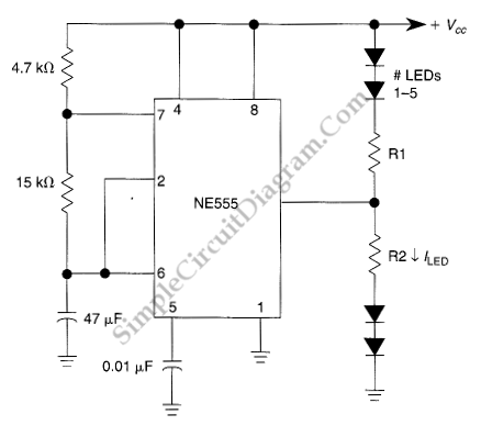
This LED flasher circuit utilizes a 555 integrated circuit (IC) and is designed to drive multiple LEDs. Notably, connecting several LEDs in series does not increase the power consumption. The LED flasher circuit based on the 555 timer IC is...
The VFC62 is a voltage-to-frequency and frequency-to-voltage converter that effectively transforms analog signals into digital signals. The digital output is presented in an open collector format, where the digital pulse repetition rate is directly proportional to the amplitude of...
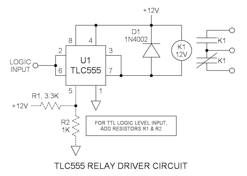
Many integrated circuits possess undocumented features or capabilities. The TLC555 output (pin 3) can sink a load of 100mA down to 1.28V. The open-drain transistor reset (pin 7) can also sink 100mA to 1V. Connecting both lines is permissible...
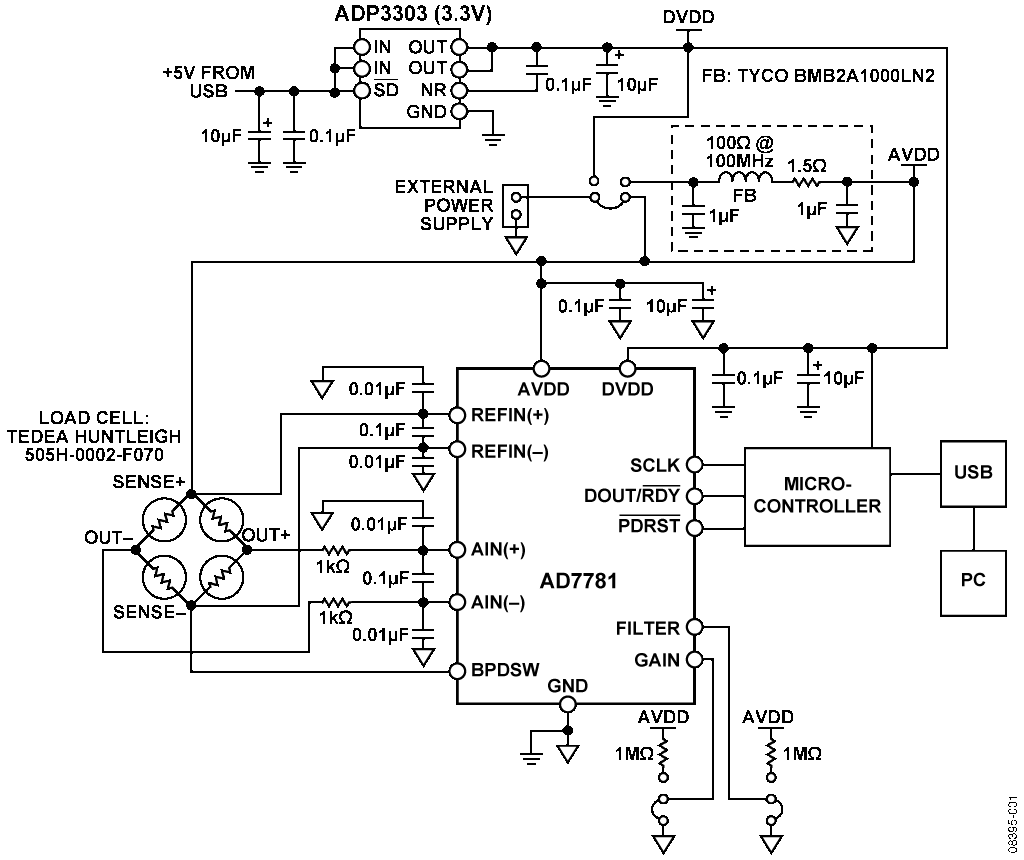
The AD7781 is a complete low-power front-end solution for bridge sensor products, including weigh scales, strain gauges, and pressure sensors. It contains a precision low-power 20-bit sigma-delta ADC, an on-chip low-noise programmable gain amplifier (PGA), and an on-chip oscillator....
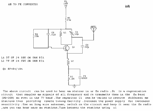
This circuit can be used to receive AM stations in an FM radio. It is a regenerative circuit that samples AM signals of all frequencies and retransmits them in the FM band or in the TV band. The described circuit...
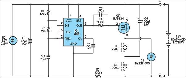
The following circuit illustrates a 6/12/24V Lead Acid Battery Charger Circuit Diagram. Features: It is essentially a high-voltage pulse generator. The circuit diagram for a 6/12/24V Lead Acid Battery Charger is designed to efficiently charge lead-acid batteries of varying voltages....