
6 Watt Hi Fi Audio Amplifier Using TDA2613
The circuit features the TDA2613 IC, which is capable of delivering up to 6 watts of output power into an 8-ohm load, making it suitable for driving small speakers in various audio applications. The amplifier operates on a single supply voltage, typically ranging from 12V to 18V, allowing for flexibility in power supply design.
Key components of the circuit include input and feedback resistors, capacitors for stability and filtering, and a heat sink for thermal management to ensure reliable operation during extended use. The input stage usually consists of a coupling capacitor that blocks DC components, allowing only the audio signal to pass through. The feedback network stabilizes the gain of the amplifier, which can be adjusted by changing the resistor values.
Additionally, the circuit may incorporate bypass capacitors to filter out any power supply noise, ensuring that the audio output remains clean and free from distortion. The TDA2613 also includes built-in protection features against short circuits and thermal overload, which enhances the reliability of the circuit in practical applications.
This audio amplifier circuit is particularly suitable for use in portable audio devices, television sets, and small home audio systems, where compact size and efficiency are critical. The straightforward design and the availability of the TDA2613 IC make it an attractive option for hobbyists and professionals alike.A 6 watt audio amplifier circuit using TDA2613 is shown here. TDA2613 is an integrated Hi-Fi audio amplifier IC from Philips Semiconductors. The IC is swi.. 🔗 External reference
Related Circuits
This instrument is a sensitive analyzer that detects changes in frequency and the width of an acoustic signal. The brightness of the LED that activates at any given moment is proportional to the width of the signal, while the...
This circuit is mainly intended to provide common home stereo amplifiers with a microphone input. The battery supply is a good compromise: in this manner the input circuit is free from mains low frequency hum pick-up and connection to...
Measures 10mV to 50Volt RMS in eight ranges. Simply connect to your Avo-meter set to 50µA range. Connect J2 and J3 to an Avo-meter set to 50µA range. Switching SW2 the four input ranges will be multiplied by 5....
This design is based on an 18 Watt Audio Amplifier and was developed primarily to address the needs of users who have difficulty locating the TLE2141C chip. It utilizes the commonly available NE5532 Dual IC; however, its power output...
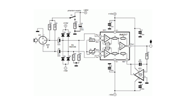
A design was published for a stereo microphone preamplifier featuring balanced inputs and a phantom power supply. The core of this circuit utilizes a specialized analog component. The stereo microphone preamplifier circuit is designed to enhance audio signals captured by...
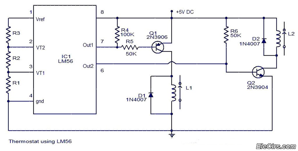
The LM56 Thermostat Project Circuit Diagram includes a schematic for the LM56 thermostat. The values of resistors R1, R2, and R3, which determine the required trip points VT1 and VT2, can be calculated using the following equations: VT1 =...