
Audio Millivoltmeter
The circuit described is a precision AC voltage measurement system designed to cover a wide range of input voltages from 10 mV to 50 V RMS, utilizing an eight-range switching mechanism for user flexibility. The device operates by connecting to an Avo-meter configured to the 50µA range, allowing for accurate current measurement corresponding to the voltage ranges selected.
The input connections, labeled J2 and J3, facilitate the integration of the Avo-meter into the circuit. The switching element, SW2, is crucial as it allows the user to select between four primary input ranges, which are then multiplied by a factor of five, effectively expanding the measurement capabilities. The full scale deflection (fsd) ranges are specifically set at 10 mV, 50 mV, 100 mV, 500 mV, 1 V, 5 V, 10 V, and 50 V, providing a comprehensive measurement spectrum.
To ensure accurate readings, particularly in the 1 V range, resistor R11 must be calibrated to indicate 1 V when a 1 V sine wave at 1 kHz is applied. This calibration step is critical for maintaining measurement precision and should be verified against a known standard, such as a precision Millivoltmeter or an oscilloscope.
The oscilloscope used for comparison should display a sine wave with a peak-to-peak amplitude of 2.828 V, corresponding to the RMS value of 2 V. The circuit also maintains a flat frequency response across the audio frequency range of 20 Hz to 20 kHz, ensuring that it can accurately measure signals without significant distortion or attenuation over this bandwidth.
For those encountering challenges in selecting resistor values for R1, R2, R3, and R4, a suggested approach is to utilize a resistor value of 10 MΩ for R1, which can serve as a starting point for further calculations and adjustments in the circuit design. This method aids in achieving the desired performance characteristics while simplifying the component selection process.Measures 10mV to 50Volt RMS in eight ranges. Simply connect to your Avo-meter set to 50µA range. Connect J2 and J3 to an Avo-meter set to 50µA range. Switching SW2 the four input ranges will be multiplied by 5. Total fsd ranges are: 10mV, 50mV, 100mV, 500mV, 1V, 5V, 10V, 50V. Set R11 to read 1V in the 1V range, with a sine wave input of 1V @ 1KHz. Compare the reading with that of another known precision Millivoltmeter or with an oscilloscope. # The oscilloscope reading must be a sinewave of 2.828V peak to peak amplitude # Frequency response is flat in the 20Hz-20KHz range # If you have difficulties in finding resistor values for R1, R2, R3 & R4, you can use the following trick: R1 = 10M 🔗 External reference
Related Circuits
The test beeper generates a sinusoidal signal with a frequency of 1,000 Hz, which is a standard test frequency for audio amplifiers. It utilizes a Wien-Bridge oscillator configuration, also referred to as a Wien-Robinson oscillator. The frequency-determining network comprises...
The Tiny Audio Amplifier kit is a good choice for battery operation. It is based on LM386 IC. Power supply - 6 - 12 VDC. Output power - 1 W, 8 Ohm. The quiescent power drain is only 24...
These accessories are low-cost, high-speed, bifet-input operational amplifiers utilizing internally compensated voltage (BI-FET II technology). They require low supply voltages while offering a wide gain bandwidth product and fast slew rate. Additionally, well-matched high voltage JFET input devices accommodate...
This is a simple circuit designed for an audio amplifier project to control the speaker output relay. The purpose of this circuit is to manage the relay that activates the speaker output in the audio amplifier. The circuit is...
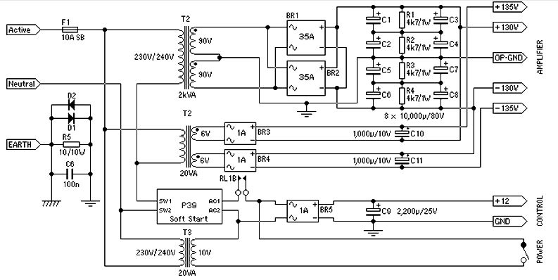
Power supply for a 1500-watt audio power amplifier. This power supply circuit is paired with a high-power audio amplifier rated at 1500 watts. A serious approach is required to design the power supply for the amplifier. First, a step-down...
The circuit incorporates an audio transformer. There is an ongoing effort to understand the concept of impedance and its significance. Clarification is sought on the necessity of an audio transformer and its function in changing impedance. An inquiry is...
Warning: include(partials/cookie-banner.php): Failed to open stream: Permission denied in /var/www/html/nextgr/view-circuit.php on line 713
Warning: include(): Failed opening 'partials/cookie-banner.php' for inclusion (include_path='.:/usr/share/php') in /var/www/html/nextgr/view-circuit.php on line 713