6 x 6 Loop Antenna
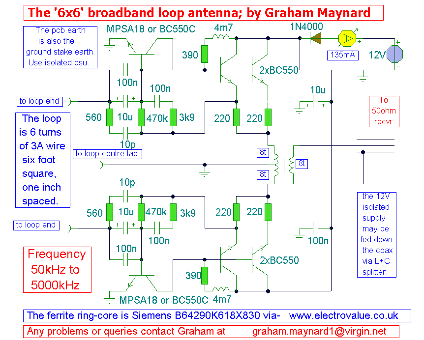
This new loop antenna designed by Graham Maynard features a six-foot square, six-turn loop that is aperiodic in nature, covering a frequency range of 50 KHz to 5000 KHz. Its size allows for inconspicuous mounting against a garden fence, minimizing interference from household sources. The design incorporates a center-tapped loop winding that functions as an input phase splitter, facilitating low distortion push-pull operation. The amplifier includes a low impedance shunt input, enhancing gain and resulting in a superior signal-to-noise ratio compared to single-ended or high impedance amplifiers. The amplifier achieves a gain of 42 to 54 dB across its frequency range. The first MPSA18 transistor operates in common emitter configuration, with the collector connected directly to a double emitter follower pair, featuring self DC biasing. The emitter of the initial BC550C transistor is coupled to the base of the MPSA18 transistor. A network of resistors and capacitors surrounding each MPSA18 transistor tailors the amplifier's response to specified limits. The double emitter follower pair effectively distributes Class A heat dissipation, while direct feedback in the bias chain mitigates temperature drift effects. The output from each amplifier half is routed through a 2:1 tri-filar wound push-pull output transformer, with the output winding sandwiched between the primary halves, ensuring equal and opposite current flow for maximum linearity. The output is isolated to minimize earth loop noise injection, whether from receiver earth leakage or loop amplifier power supply earth leakage. A separate twin flex (speaker wire) can be used to power the amplifier, although it is also compatible with a mains power supply via the coaxial cable. Graham recommends the UNI550R mains power supply from Electrovalue (8+p/p). The overall phase response remains relatively flat across the frequency bands, allowing for stable reception patterns, which is beneficial for trans-oceanic medium wave reception. The center tap should be located at the midpoint along the bottom six-foot antenna span and can be grounded with an earth stake to potentially enhance reception on certain bands. It is advisable to experiment with the grounding of the center tap to determine its effect on reception quality. For stability, the component layout should adhere to the specified circuit design, with short and thick signal ground connections centralized on the PCB. This antenna is intended for sensitive DXing applications and may experience overload if positioned too close to a local broadcast transmitter. To nullify powerful signals, the loop should be oriented at right angles to their source, aligning the loop's winding axis with the interference.
The loop antenna design described utilizes a sophisticated configuration that enhances its performance across a wide frequency spectrum. The six-foot square loop, with its six turns, is optimized for various radio frequencies, making it suitable for both amateur and professional radio applications. The aperiodic nature of the loop allows it to operate effectively without the need for tuning, providing a broad bandwidth that is advantageous for receiving diverse signals.
The amplifier section is a critical component of the design, utilizing a combination of MPSA18 and BC550C transistors to achieve high gain and low distortion. The common emitter configuration of the MPSA18 transistors ensures that the input signal is amplified efficiently. The double emitter follower stage serves to buffer the output, providing a low impedance output that can drive subsequent stages or loads effectively.
The inclusion of a tri-filar wound push-pull output transformer is a notable feature, as it enhances linearity and reduces harmonic distortion. This transformer configuration allows for balanced output, which is essential for maintaining signal integrity, especially in sensitive applications such as DXing. The isolation of the output further protects against unwanted noise, ensuring that the received signals remain clear and discernible.
Grounding the center tap at the midpoint of the antenna is a practical consideration that can influence reception quality. By experimenting with grounding, users can optimize the antenna's performance for specific frequency bands, potentially reducing noise and improving signal clarity.
In summary, this loop antenna design represents a well-thought-out approach to radio reception, combining innovative amplifier design with practical antenna construction techniques. The careful attention to component selection and layout contributes to its effectiveness in a variety of operating conditions, making it a valuable tool for radio enthusiasts and professionals alike.This new loop antenna by Graham Maynard is his best design yet and I am proud to be the first to present his work. It uses one, six foot square, six turn loop, and is aperiodic in nature, covering the frequency range 50KHz - 5000KHz.
The loop is of a size that can be mounted inconspicuously against a garden fence away from household interferences. This new `6x6` design uses the centre tapped loop winding as an input phase splitter. This ensures low distortion push-pull operation. The amplifier also has a low impedance shunt input which maximises gain. These aspects give it a better signal to noise ratio than with a single ended or high impedance amplifier. The amplifier provides a useful gain of 42 - 54dB over its frequency range, see the Bode Plot below. Please note, that the Bode plot is derived for the amplifier circuit ONLY, it is not possible to simulate the characteristics of a six foot square loop.
The first MPSA18 transistor on each loop operates in common emitter, the collector being directly coupled to a double emitter follower pair. The circuit has self DC biasing, the emitter of the first BC550C being coupled to the base of the MPSA18 transistor.
The network of resistors and capacitors around the base of each MPSA18 transistor tailors the amplifier response to the specified limits. The double emitter follower pair evenly distributes the Class A heat dissipation, and direct feedback in the bias chain, counters temperature drift effects.
The output from each amplifier half is fed via a 2:1 tri-filar wound push-pull output transformer, with the output winding sandwiched between each primary half. There is equal but opposite current flow and therefore maximum linearity. The output is isolated, which minimizes earth loop noise injection, either via receiver earth leakage or loop amplifier psu earth leakage.
To power the amplifier a separate twin flex may be used (speaker wire), though it is possible to use a mains PSU via the coax itself. Graham`s recommended mains psu is the UNI550R from Electrovalue (8+p/p) The overall phase response is reasonably flat throughout any band, thus any cardioid or other developed reception patterns can remain directionally stable over a decent frequency range, which might be useful for trans-oceanic MW reception.
It is intended that the centre-tap be made at the mid point along the bottom six foot antenna span, and this may be grounded with an earth stake. Sometimes reception on some bands can be made quieter by grounding this centre tap. You should to try the `6x6` with and without the ground on your favourite band. To ensure stability, the component layout should follow the above circuit layout, with all signal ground connections being kept as short and thick as possible in the centre of the pcb.
This is of course a sensitive DXing antenna, thus it might be overloaded if used too close to a local broadcast transmitter. You can null powerful signals by setting the loop up at right angles to their source, i. e. when the loop`s winding axis is in line with the interference. 🔗 External reference
