
Computer-Controlled 4-20mA Current Loop
The 4-20 mA current loop is a standard method for transmitting analog signals in industrial environments, particularly for process control and instrumentation applications. The current loop operates on the principle of varying current levels to represent different values of a physical measurement, such as temperature, pressure, or flow rate.
In this system, 4 mA typically represents the lowest end of the measurement range, while 20 mA signifies the highest end. This range provides a clear distinction between the minimum and maximum values, allowing for accurate monitoring and control of the equipment. The choice of a 4-20 mA loop is advantageous due to its inherent noise immunity, as the current remains constant regardless of the resistance of the transmission line, thus ensuring reliable signal integrity over long distances.
The current loop consists of a transmitter, which converts the physical measurement into a corresponding current signal, and a receiver, which interprets this signal to control the equipment accordingly. The transmitter may be a sensor or a transducer that is calibrated to output a specific current based on the measured variable. The receiver can be a programmable logic controller (PLC), a digital display, or any other control system capable of processing the current signal.
Powering the loop can be accomplished through a variety of methods, including using a dedicated power supply or a loop-powered device that draws its operating power from the current loop itself. This configuration simplifies installation and reduces the need for additional wiring.
In summary, the computer-controlled 4-20 mA current loop is a robust and reliable method for transmitting analog signals in industrial applications, facilitating effective equipment control and monitoring.In some industries, to control the some equipments they are use computer-controlled 4-20mA current loop. This current loop is used transmit a signal over a.. 🔗 External reference
Related Circuits
While working on an Electricity/Electronics exhibit for the Museum of Science in Boston, a number of significant issues were discovered in explaining basic electricity. One major problem was the obscure manner in which exhibit devices typically present electrical effects:...
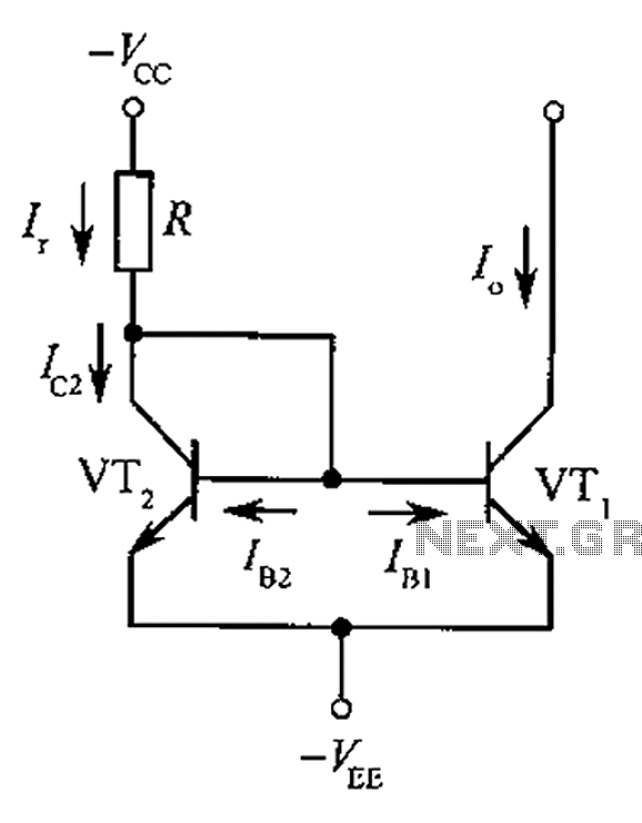
The circuit depicted is a mirror substantially constant current source circuit, in which transistors VT1 and VT2 are matched to each other. The figure illustrates that the current through Ir is equal to Ic2 plus the sum of base...
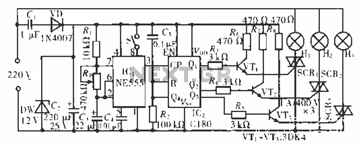
The circuit operates at 220 V AC using a C1 buck converter and a DW regulator. The VD ensures the entire stream is processed, and C2 provides a filtered output of 12 V DC for the voltage supply control...
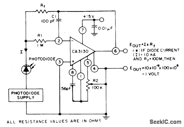
The circuit employs three CA3130 BiMOS operational amplifiers in an application that is sensitive to sub-picoampere input currents. It generates a ground-referenced output voltage that is proportional to the input current flowing through the photodiode. The described circuit utilizes three...
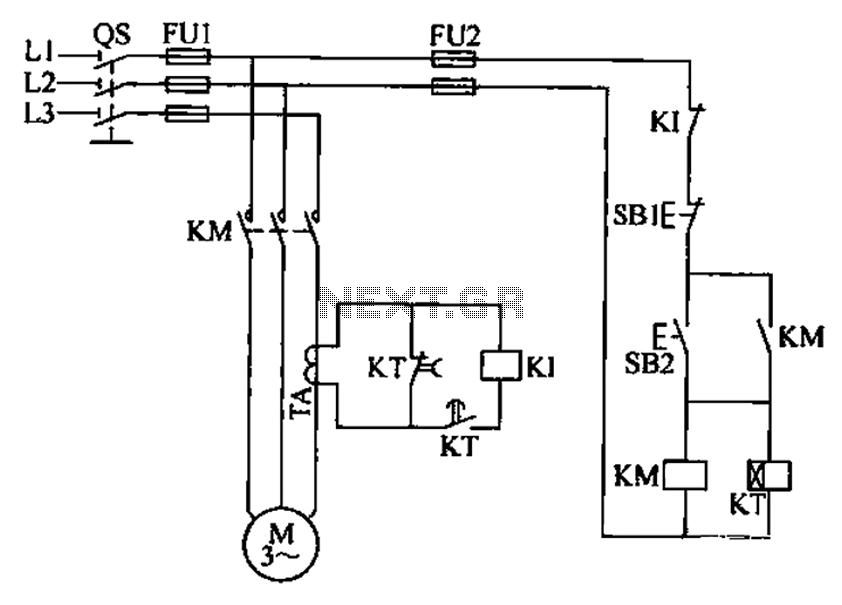
A three-phase electric motor overcurrent protection circuit. This example circuit utilizes a transformer to monitor the current, ensuring that the currents in the three-phase motor do not exceed normal operating levels. When the current exceeds the set threshold, the...
Many analog ohm meters have a non-linear scale, which results in poorer resolution at higher resistance values. This is due to the use of inexpensive current sources. Many analog ohm meters operate on a principle where the scale is not...