
The current loop interface circuit diagram of AD694 being used as D / A converter
The AD694 current loop interface circuit is designed to facilitate efficient communication between digital systems and analog devices. The architecture allows for seamless conversion from digital signals to analog outputs, which is crucial in various applications such as industrial automation, process control, and sensor interfacing.
The AD566A DAC, which is integral to this circuit, features a 12-bit resolution, enabling it to produce 4096 discrete output levels. This high-speed DAC ensures rapid conversion times, making it suitable for applications requiring quick response rates. The connection of the DAC output to the UI-end of the AD694 allows for direct integration, enhancing the overall performance of the signal conditioning process.
The dual ±15V power supplies are essential for the operation of the AD694, providing the necessary voltage levels for accurate signal processing and conditioning. The reference voltage supplied to the AD566A is critical for maintaining the precision of the output signal, ensuring that the DAC operates within its specified parameters.
The internal resistor network of the AD566A is a key feature that allows for the adjustment of the full-scale input to 10V. This configuration is particularly useful in applications where specific voltage levels are required for accurate signal representation. The inclusion of a frequency compensation capacitor (C2) helps stabilize the output by mitigating potential oscillations and ensuring consistent performance across various operating conditions.
The full-scale adjusting potentiometer (RP) provides flexibility in tuning the output signal, allowing users to calibrate the circuit according to their specific requirements. The design eliminates the need for a fixed resistor, simplifying the setup and enhancing the adaptability of the circuit.
Overall, the current loop interface circuit of the AD694, in conjunction with the AD566A DAC, represents a robust solution for digital-to-analog conversion in sensor signal conditioning applications, ensuring high accuracy and reliability in various electronic systems.The current loop interface circuit diagram of AD694 multi-functional sensor signal conditioner being used as D / A converter. The current loop interface of AD694 being used as D / A converter (DAC) can achieve the conversion of digitalvalue †’voltage signal †’current signal.
DAC`s current loop interface circuit is shown as the chart. AD566A is high-speed 12-bit DAC, its output (DAC OUT) is connected to AD694`s UI-end, UI + is grounded. AD694 uses ± 15V dual supplies, and provides reference voltage to the AD566A. Internal resistor network of AD566A will set AD694 with 10V full scale input. C2 is the frequency compensation capacitor. RP is the full scale adjusting potentiometer, it has no need to use a fixed adjustment 50 © resistor to replace the potentiometer. 🔗 External reference
Related Circuits
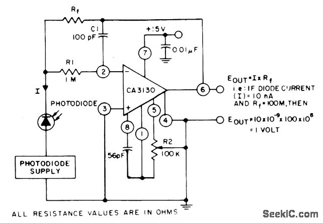
The circuit employs three CA3130 BiMOS operational amplifiers in an application that is sensitive to sub-picoampere input currents. It generates a ground-referenced output voltage that is proportional to the input current flowing through the photodiode. The described circuit utilizes three...
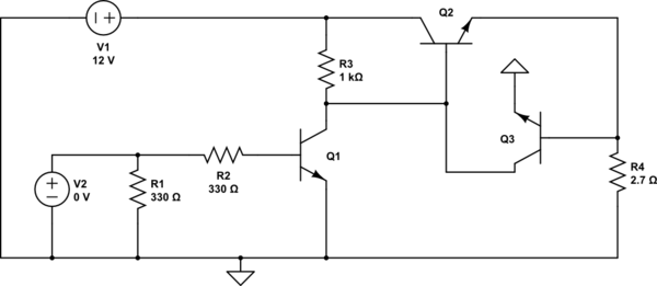
The second transistor (T2) is activated by the current passing through the resistor (R1). When a DALI slave unit is connected, this current matches the current flowing through the power transistor (T1). The resistor's value is selected so that...
This example describes the use of HS101 and HS201 radio transmitter and receiver modules to control rotating color lights, functioning as a multi-channel radio remote control device suitable for small dance floors or home use. Users positioned at any...
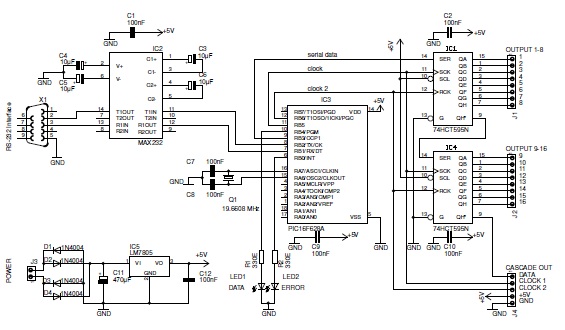
This basic PIC-based RS-232 serial interface can control up to 120 digital TTL outputs. The described circuit utilizes a PIC microcontroller to facilitate communication via the RS-232 protocol, which is a standard for serial communication. The interface primarily serves to...
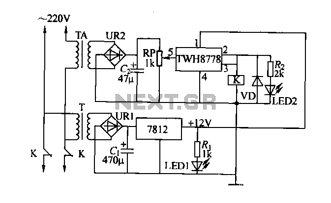
An electric power limiter circuit restricts the user load, ensuring that household appliances operate within a specified normal current range. When the load exceeds a predetermined threshold, the power supply is disconnected. This circuit utilizes the high-power integrated TWH8778...
Pressing the pushbutton on the transmitter activates a sound and/or light alert in the receiver. This system operates without wiring or radio frequencies; instead, the transmitted signal is conveyed through the mains supply line. It is suitable for use...
Warning: include(partials/cookie-banner.php): Failed to open stream: Permission denied in /var/www/html/nextgr/view-circuit.php on line 713
Warning: include(): Failed opening 'partials/cookie-banner.php' for inclusion (include_path='.:/usr/share/php') in /var/www/html/nextgr/view-circuit.php on line 713