
60 Watt Bass Amplifier
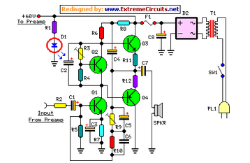
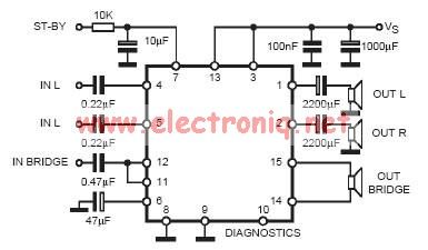
The described circuit is a power amplifier designed to deliver high-quality audio output with adjustable low-cut and bass controls. The low-cut control allows users to filter out unwanted low-frequency signals, which can enhance clarity and reduce distortion in the audio output. The bass control provides the ability to boost or attenuate low-frequency signals, allowing for customization of the audio experience based on personal preference or specific acoustic environments.
The output power specification indicates that the amplifier can deliver 40W into an 8 Ohm load, which is typical for consumer audio applications, ensuring compatibility with standard speakers. Additionally, the capability to provide 60W into a 4 Ohm load suggests that the amplifier can drive lower impedance speakers effectively, delivering more power and potentially higher sound levels without distortion.
The circuit topology employed in this design is likely to be a Class AB amplifier configuration, which is favored for its balance between efficiency and sound quality. This topology allows for a linear amplification of audio signals, minimizing crossover distortion while providing sufficient output power. Key components of the circuit may include transistors for amplification, resistors for biasing, capacitors for coupling and decoupling, and potentiometers for user-adjustable controls.
Overall, this power amplifier design is well-suited for a variety of audio applications, from home audio systems to professional sound reinforcement, providing both flexibility in sound shaping and reliable performance across different load impedances.Low-cut and Bass controls, Output power: 40W into 8 Ohm and 60W into 4 Ohm loads This design adopts a well established circuit topology for the power ampl.. 🔗 External reference
Related Circuits
Turns off your amplifier when idle for 15 minutes. Fed by amplifier tape-output. This circuit turns off an amplifier or any other device when a low-level audio signal fed to its input is absent for 15 minutes at least....
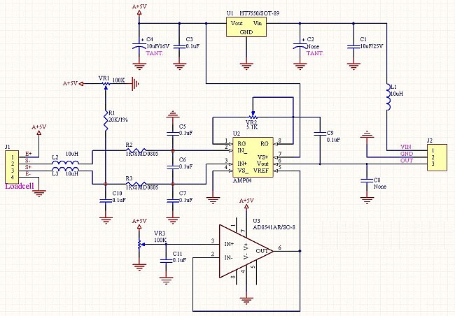
The following circuit illustrates the AD854 integrated circuit used in a load cell amplifier circuit diagram. Features include a 6V gel cell battery charger and a 5V regulated solar cell. The AD854 is a precision, low-power operational amplifier (op-amp) that...
This complete aerial quality, low noise address audio amplifier is based on the Hybrid Integrated Circuit STK4050 manufactured by Sanyo. The circuit incorporates all necessary components and has a maximum output power of 200W. It features an onboard power...
In practical applications, a series resistance must always be included. This component serves the dual purpose of limiting the current at pin 7 and smoothing the ON/OFF transitions during standby. In electronic circuits, particularly those involving integrated circuits (ICs) or...
The power requirements for driving light aircraft flight simulator transducers are relatively low, approximately 20W (real Watts, RMS power). It is essential to ensure that the amplifier circuit has adequate low-frequency bandwidth. Single-ended amplifiers with capacitive coupling between the...
The circuit utilizes two 2N3819 FETs arranged in a cascode configuration. The lower FET functions in common source mode, while the upper FET operates in common gate mode, achieving full high-frequency gain. The lower FET is adjustable, enabling tuning...