
Transducer amplifier circuit

The described circuit focuses on driving transducers for light aircraft flight simulation, emphasizing the importance of low-frequency response and efficient power management. The choice of using BTL configuration with the TDA1554Q amplifier allows for effective utilization of space and components while providing adequate power output for various transducer types. The circuit design incorporates a low-pass filter to ensure that higher frequency signals do not interfere with the operation of the transducers, which are primarily designed to reproduce low-frequency effects. The volume control mechanism is also tailored to allow for individual adjustments, enhancing the user experience by providing flexibility in sound output.
The power supply considerations are critical, as the circuit requires a stable 12V supply capable of delivering sufficient current to meet the demands of the transducers. The use of a switch-mode power supply provides an efficient and compact solution, minimizing heat generation and maximizing reliability. The design also takes into account the need for proper grounding and shielding, particularly when connecting volume potentiometers to minimize noise and interference.
In summary, the circuit design is a well-thought-out approach to driving flight simulator transducers, balancing performance, component availability, and user adjustability while ensuring that the power supply meets the necessary demands for optimal operation.The power requirements for driving light aircraft flightsim transducers is not so high; about 20W (real Watts, RMS power). Attention has to be paid to the amplifier circuit to make sure that the amplifier has sufficient low frequency bandwidth.
Single ended amplifiers with capacitive coupling between amplifier and speaker would require very large capacitor values to reach 5Hz. Amplifiers with direct coupling between amplifier and speaker are preferred. You can either go for amps that have + and – supply that drive a speaker to ground reference, or you can choose Bridge Tied Load (BTL) structure, where the speaker is connected between two amps, where the amps have opposite polarity. BTL is most easy, supply- and component-wise. Building small power amplifiers is very easy with currently available IC amplifiers. They require very few external components, have various protections build-in and are cheap. You can choose from SGS-Thompson, Philips Semiconductors, National Semiconductors to name a few. For my transducers I used Philips TDA1554Q which in BTL configuration has two channels. As I wanted to adjust the "volume" of each transducer function separately, I used 2 IC ’s, leaving me with one unused channel.
(You could use this channel for driving a separate subwoofer). Subwoofers and transducers do not really need stereo information, so I mixed Left and Right together, added a low pass filter stage and then dedicated volume adjustment for each transducer. The TDA1554Q is a class B output amplifier, with 4 power amps in one 17 pin plastic power package. Manufacturer: Philips Semiconductors. Go to and type "TDA1554Q" in the search box. You will also be able to find all similar devices. Pins 9 and 15 are not connected. Connect the other pins as shown. Capacitors on the supply (470uF and 0. 1uF) need to be close to the IC. Keep in mind that the electrolitic capacitors have polarity (see top one). Although the amp outputs and speakers have polarity as well, it does not make a difference how you connect them, as transducers are on separate areas anyway, so do not cancel.
For the volume potmeters, I used the PCB mounted type, not wired to the front. If you wire them to a front panel, you need to use shielded cable. (Ground = shield) I needed the gain stage as my sound card (Sound blaster 16) did not have sufficient output signal to fully drive the output amplifier, which has a gain of 26 dB (20x). The max power that each transducer can receive from the amplifier depends on the amplifier supply voltage: (2x higher voltage is about 4x higher power) and speaker impedance: (2x higher impedance is about 2x lower power).
With supply voltage +12V and speaker impedance shown, the 4 Ohm chair speaker receives about 15W max, the 8Ohm throttle speaker about 8W max, and each 4 Ohm pedal speaker about 4W max (they are in series). The 12V supply needs to be able to deliver about 4 Amps max. I used a 70W switch mode power supply "brick" as used for notebooks. They are getting cheap, and are (mostly) short circuit proof. If you use a higher gain output amplifier, (45dB or so), the gain stage can be omitted, and replaced by simple passive low pass filter as shown below.
This assumes a sound card output with reasonably low output impedance (<100 Ohm, most of them are able to drive headphones, so should be OK) The passive low pass filter rolls of at 60Hz. I did not build this circuit as I could not get the TDA1557Q IC, but it should work. For IC spec, go to the Philips Semiconductors web site mentioned earlier. Note on the supply capacitor (470uF) for each IC: If you don ’t use a switch mode power supply "brick" but ordinary transformer with diode bridge, the capacitor value needs to be increased dramatically, about 2200uF/25V type per IC. All of my circuits are build on experiment boards, placing the components in a logic fashion and connecting them with solder (for adjacent pads) or 0.
3m 🔗 External reference
Related Circuits
This type of design can produce a very high amperage current for a fraction of a second that can be used to do some useful work if properly harnessed. A point to remember is that Paul Baumann built his...
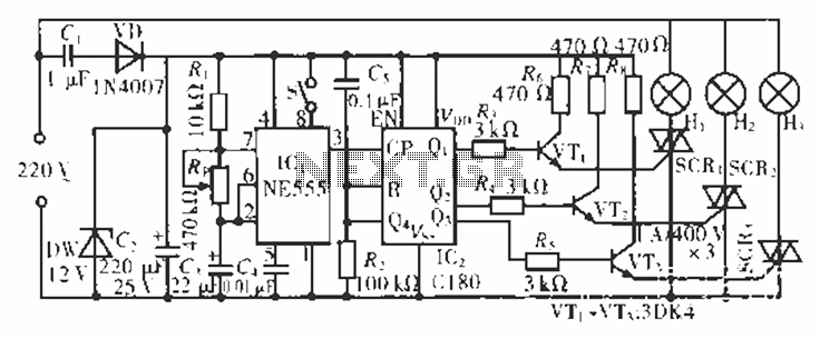
The circuit operates at 220 V AC using a C1 buck converter and a DW regulator. The VD ensures the entire stream is processed, and C2 provides a filtered output of 12 V DC for the voltage supply control...
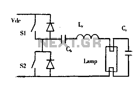
The construction of buildings, when full power is not required, utilizes dimmable electronic ballasts for continuous fluorescent operation, which can further reduce power consumption. Most modern designs and research on electronic ballasts recommend using resonant converter power circuits to...
This circuit functions as a camera switch, allowing multiple cameras to be connected to a single monitor. It can operate in both manual and automatic modes. In automatic mode, the circuit utilizes a 555 astable multivibrator to generate a...
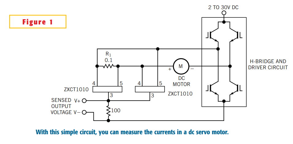
The simple circuit design in Figure 1 lets you measure all components of a current flowing in a dc servo motor. The rectified output of the circuit uses ground as a reference, so you can measure the output by...
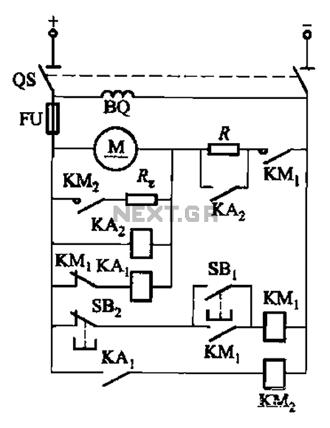
The circuit illustrated in Figure 3-196 features a starting resistance level and an undervoltage relay (KAz) that is controlled by the removal of the startup resistor. It also includes dynamic braking for shutdown purposes. The undervoltage relay (KAL) operates...