
60 Watt Guitar Amplifier

This power amplifier circuit design is characterized by its efficient use of a single-rail power supply, which simplifies the overall architecture while maintaining high performance levels. The capacitor coupling method employed for the speakers not only facilitates the necessary AC signal transmission but also serves as a protective barrier against DC faults that could potentially damage the loudspeakers. The integration of a two-transistor gain block in the preamplifier stage allows for substantial voltage gain, enhancing the amplifier's ability to handle high input signals without distortion.
The choice of output transistors is critical; while Darlington pairs are known for their high current gain, their size can lead to inefficiencies in this specific application. The suggested alternatives (MJ11014, MJ11013, TIP142, and TIP147) provide a balance between performance and size, ensuring that the amplifier operates within its optimal range without unnecessary excess.
The inclusion of Schottky-barrier diodes for protection against back EMF and other transients is a standard practice in amplifier design. However, opting for 1N4148 diodes softens the harmonic distortion characteristics, which may be desirable in a guitar amplifier context where musicality and tonal quality are paramount.
Thermal management is another crucial aspect of this design. The close thermal coupling of the sensing transistor (Q2) to the output transistors enables accurate temperature feedback, ensuring that the circuit can respond effectively to changes in operating conditions. This is vital for maintaining performance and reliability under varying load conditions.
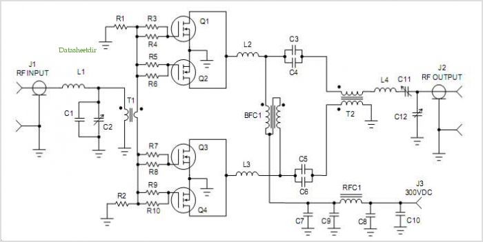
Finally, the adjustment of resistor R9 to achieve a specific voltage across C7 is essential for optimizing the amplifier's performance. Using an oscilloscope for this calibration allows for precise adjustments, ensuring that the output waveform remains symmetrical and free from unwanted clipping, which is particularly important for maintaining audio fidelity at high power levels. This attention to detail in both component selection and circuit configuration contributes to a robust and effective guitar amplifier design.This design adopts a well established circuit topology for the power amplifier, using a single-rail supply of about 60V and capacitor-coupling for the speaker(s). The advantages for a guitar amplifier are the very simple circuitry, even for comparatively high power outputs, and a certain built-in degree of loudspeaker protection, due to capacitor
C8, preventing the voltage supply to be conveyed into loudspeakers in case of output transistors` failure. The preamp is powered by the same 60V rails as the power amplifier, allowing to implement a two-transistors gain-block capable of delivering about 20V RMS output.
This provides a very high input overload capability. The Darlington transistor types listed could be too oversized for such a design. You can substitute them with MJ11014 (Q3) and MJ11013 (Q4) or TIP142 (Q3) and TIP147 (Q4). D1 and D2 can be any Schottky-barrier diode types. With these devices, the harmonic modifier operation will be hard. Using for D1 and D2 two common 1N4148 silicon diodes, the harmonic modifier operation will be softer. In all cases where Darlington transistors are used as the output devices it is essential that the sensing transistor (Q2) should be in as close thermal contact with the output transistors as possible.
Therefore a TO126-case transistor type was chosen for easy bolting on the heatsink, very close to the output pair. R9 must be trimmed in order to measure about half the voltage supply across the positive lead of C7 and ground.
A better setting can be done using an oscilloscope, in order to obtain a symmetrical clipping of the output wave form at maximum output power. 🔗 External reference
Related Circuits
Since the volume control is after the gain stage, the preamp can be easily overloaded. I tried to limit the input signal by mounting a 470 k resistor in series with the CD input. A voltage divider is formed...
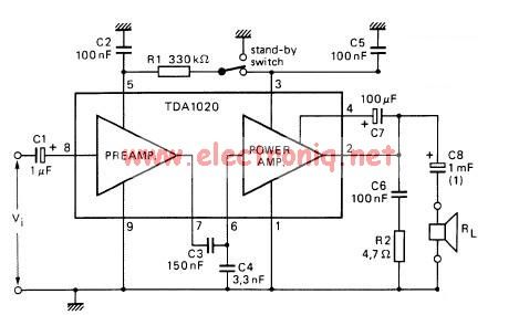
The TDA1020 is a monolithic integrated 12 W audio amplifier housed in a 9-lead single in-line (SIL) plastic package. Although it is designed primarily for car audio applications, it can also be utilized in various other audio applications. The TDA1020...
There are instances where long cable runs from the pedalboard to the amplifier are necessary, or a more robust driving circuit is required to handle the heavy load presented by parallel devices. A suitable solution is a buffer box....
This amplifier circuit is designed to enhance TV signals in the UHF range. It employs a low-noise transistor, providing an amplification of 10 to 15 dB within the frequency spectrum of 400 MHz to 850 MHz. It is crucial...
This preamplifier is a requirement resulting from many friends to provide a high-quality preamplifier, capable of driving high-quality power amplifiers with good sound. It is not, however, difficult to make; it combines simplicity and handiness. It does not allocate...
The LinkSwitch-TN supply LNK306PN provides a constant current output of up to 9 W at a maximum output voltage of 70 VDC, making it suitable for driving LEDs. A passive valley-fill power factor correction (PFC) circuit ensures the supply...