
Battery Powered Electret Microphone Pre-Amplifier
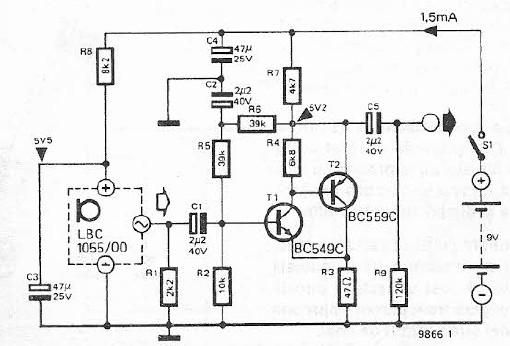
The electret microphone pre-amplifier circuit is designed to amplify the weak audio signals generated by an electret microphone. The LMV721 op-amp serves as the core amplification component due to its favorable specifications, including low noise operation and minimal power consumption, making it suitable for battery-powered applications.
The circuit typically includes the electret microphone, which contains a built-in FET that converts sound waves into electrical signals. The output from the microphone is connected to the non-inverting input of the LMV721. A resistor-capacitor (RC) network may be employed to filter out high-frequency noise and stabilize the gain. The gain of the amplifier can be adjusted by selecting appropriate feedback and input resistors.
Power supply considerations are critical; the LMV721 can operate with a single supply voltage, which simplifies the design. Bypass capacitors are recommended close to the power supply pins of the op-amp to reduce power supply noise. The output of the LMV721 can then be interfaced with further audio processing stages or directly with an analog-to-digital converter (ADC) for digital audio applications.
Overall, this schematic provides an efficient solution for amplifying audio signals in various applications, including voice recognition systems, portable audio devices, and other low-power audio applications.Here is a schematic diagram of electret microphone pre-amplifier using LMV721 op-amp. because the LMV721 has low noise and low power features, it would be an. 🔗 External reference
Related Circuits
This relatively simple mixer was designed for three dynamic microphones, but can be re-designed for more or less. Level and tone controls are available to tailor the sound to your needs. More: R1-R3 are level controls. R9 and R11...
Photo. This is the test circuit -the basic driver is only two transistors, two resistors, the circuit was evaluated using a white LED, but when it was time to button it up and archive it, I replaced the expensive...
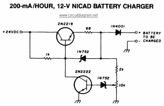
A 12V NiCAD battery charger circuit with a charging rate of 200mA per hour. This circuit initially charges the battery at 75mA until it reaches a full charge, after which the current is reduced to a trickle rate. The...
This electret microphone amplifier is constructed using standard electronic components. It is designed to work with an electret microphone capsule, although it can also accommodate a dynamic microphone that has low resistance. The circuit operates with a supply voltage...
Here we use the PIC16711. Rechargeable battery capacity is rated in mAH (milliampere-hours). The total capacity of a battery is defined as "C", that is it can supply C mA for 1 hour, or 2C for 30 minutes etc....
The hobby circuit described can be connected to a 3V battery to provide a warning when the battery is nearing its end of life. It will flash an LED when the battery voltage drops to approximately 2.4 volts. The...