
Middle Frequency Equalizer with Parametric Feature

The equalizer circuit described operates by manipulating audio signals to enhance sound quality and clarity. The NE5532 operational amplifier serves as the backbone of the design, providing low noise and high fidelity. The circuit architecture typically includes passive components such as resistors and capacitors, which define the frequency response characteristics and allow for selective boosting or attenuation of specific frequency ranges.
In the bass section, the circuit utilizes a bandpass filter configuration that allows frequencies from 20 Hz to 1 kHz to be adjusted. The resistor R5 plays a critical role in determining the gain for lower frequencies, ensuring that bass notes are rich and full without distortion. The treble section, on the other hand, is designed to handle frequencies from 1 kHz to 20 kHz, with R2 fine-tuning the high-frequency response to achieve a desirable crispness in sound.
The mid-frequency section introduces more complexity, as it utilizes a parametric equalization approach. This allows for precise control over the center frequency, which is typically set around 1 kHz to 3 kHz, where many vocal and instrumental elements reside. R11 adjusts the gain at this frequency, while R10 allows for bandwidth adjustments, enabling the user to either narrow or widen the frequency range affected by the mid boost or cut.
The overall design ensures that the equalizer can adapt to various audio sources and environments, making it a versatile tool in both live sound and studio settings. By providing the ability to sculpt sound, the equalizer enhances the listening experience, making it an indispensable component in modern audio systems.Equalizer a passive or an active electronic element or circuits (like tone control) used for the reason of altering or flattening the frequency response characteristics of a system NE5532 an internally compensated low noise dual operational amplifier with features such as full power bandwidth up to 140 KHz, input noise voltage of 8 nV, com mon mode rejection ratio, 9 V/us slew rate, high DC voltage gain, 32 V peak to peak voltage swing, wide supply voltage range from 3 V to 12 V, unity gain bandwidth at 10 MHz, and internal frequency compensation The circuit can be used with any other audio circuit although it is normally connected to the microphone line balance unit. The circuit is comprised of two parts having a typical bass and treble circuit and a parametric circuit of mid frequencies.
The circuit of the equalizer will take an audio output, and manually boosting or attenuating the amplitude by adjusting the two channels consisting of the bass with 20 HZ to 1 KHz and the treble with 1 KHz to 20 KHz. With 18 dB at 20 KHz, the high frequencies are regulated by R2 while the low frequencies are regulated by R5.
At 15 dB, the middle frequency is regulated by R11 while the center of middle frequency at 200 Hz to 6 KHz is regulated by R10. The level of the bass is controlled below a certain frequency while treble changes are made above a certain frequency.
The equalization of mid frequency rises to a maximum at its center frequency which will quickly fall off again to a flat response while passing all frequencies. Nevertheless, the output of the equalizer circuit provides sufficient amplification to a speaker. One of the handiest audio tools for videography is the use of the equalizer to eliminate problems in some soundtracks.
They can be located in a rack full of audio processors or in an audio mixer. They are used to assist in the elimination of unwanted noise, capture a horrible audio buzz, to control the audio tonal balance, and decrease the tape hiss. This type of equalizer circuit is commonly used in stereo receivers and small audio mixers. 🔗 External reference
Related Circuits
This very simple counter can be used to measure the frequency of various wireless devices. Applies in reviving the transmitter and its operation as a control monitor frequency. It can be used as a scale to the receiver. Due...
A PLL oscillator, or phase-locked loop oscillator, is a control method that compares a controlled system or plant to a reference signal. A phase-locked loop (PLL) oscillator is a sophisticated electronic circuit designed to synchronize an output signal's phase and...
Power the frequency counter and adjust the coarse (top pot) and fine (bottom pot) controls to display zero frequency. Turn the pots counter-clockwise to achieve a zero reading. Occasionally, the counter may show only squares without digits. If this...
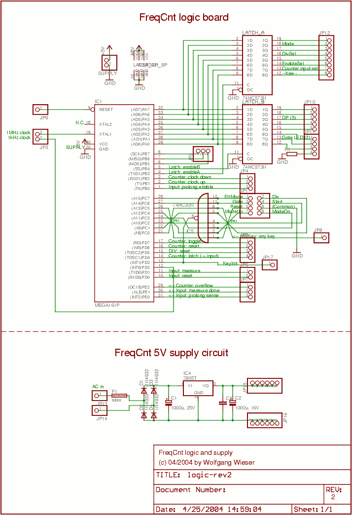
The lower schematic represents a standard bidirectional rectifier along with capacitors and a 7805 voltage regulator, which provides a stable 5V source to power the electronic components of the frequency counter. A fuse is included for security purposes. The...
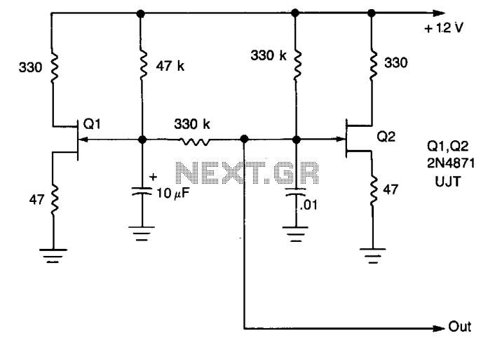
A low-frequency oscillator (Q1) modulates a high-frequency oscillator (Q2) along with its associated timing capacitor. The output frequency varies continuously. The circuit comprises two primary components: the low-frequency oscillator (Q1) and the high-frequency oscillator (Q2). The low-frequency oscillator is responsible...
A fully parametric tube equalizer (EQ) design aims to merge two schematics into one. The goal is to create a tube-based gyrator section with adjustable Q, frequency, and gain while utilizing integrated circuits (ICs) for the input and follower...