
Simple but reliable car battery tester
The LM3914 is a bar graph/LED dot display driver that can drive up to ten LEDs in either a bar or dot mode, providing a visual representation of the input voltage level. The IC operates within a voltage range of 4V to 12V, making it versatile for various applications. The input voltage is applied to the reference pin, and the output pins are connected to the LEDs. The internal voltage reference allows the LM3914 to scale the input voltage to the LED outputs effectively.
In a typical application circuit, the input voltage is fed into the LM3914 through a resistor, which sets the current for the LEDs. The output can be configured to operate in either a dot mode, where only one LED lights up at the input voltage level, or a bar mode, where multiple LEDs light up in succession to indicate the level. This feature can be particularly useful in applications such as battery level indicators, audio level meters, or any system where visual feedback of voltage levels is required.
To enhance the functionality, external components such as potentiometers can be added to adjust the reference voltage, allowing for calibration of the voltage range displayed. Additionally, capacitors may be included for noise filtering to ensure stable operation in environments with electrical noise.
The LM3914 is ideal for educational projects and prototypes due to its ease of use and minimal required components, making it a valuable component in various electronic designs.This circuit uses the popular and easy to find LM3914 IC. This IC is very simple to drive, needs no voltage regulators (it has a built in voltage regulator) and can be powered from almost every source 🔗 External reference
Related Circuits
This circuit is designed for applications where over-current protection is necessary. An example can be found in the model train hobby. Experienced model train enthusiasts understand that troubleshooting a short-circuit can be quite challenging. While it is relatively easy...
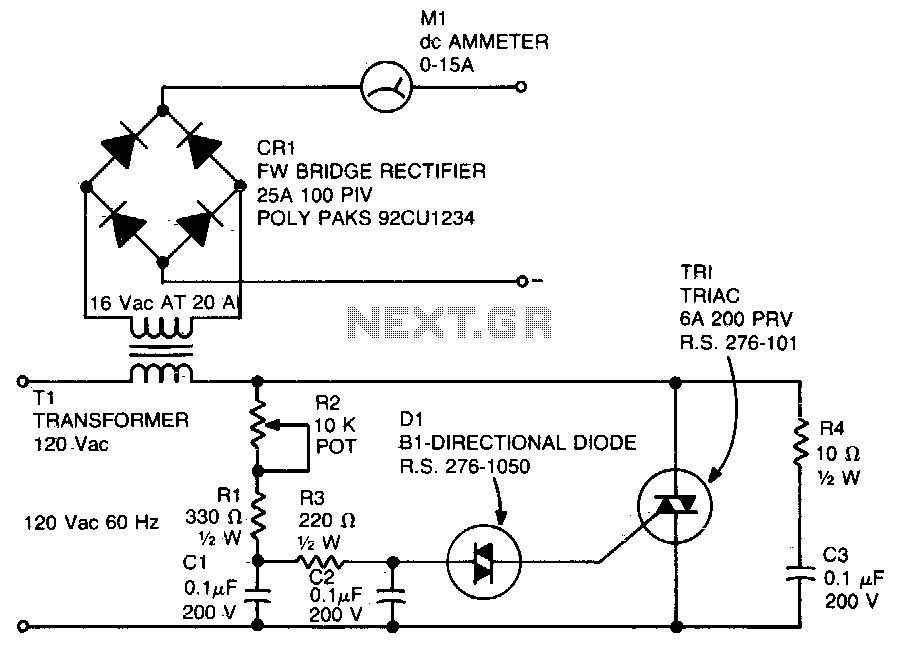
A diac is utilized in the gate circuit to enable operation for the signal applied to the gate. R1 sets a threshold level for triggering the triac. C3 and R4 are chosen to restrict the maximum charging current, forming...
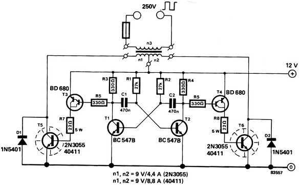
A power inverter converts direct current (DC) power to standard alternating current (AC) power. The following schematic illustrates a 12V power inverter circuit diagram. The 12V power inverter circuit typically consists of several key components that work together to achieve...
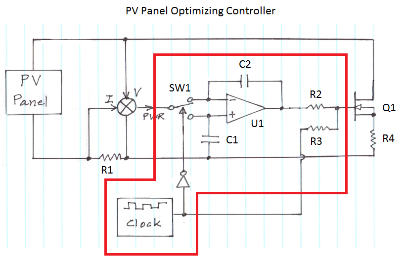
The figure illustrates the voltage-current (V-I) curve for a typical solar panel (Sharp ND-224U1F) and its output power under varying lighting conditions. The solar panel operates as a constant current source at high currents and as a voltage source...
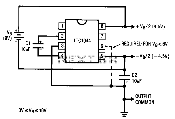
A common requirement in many systems is to obtain both positive and negative supplies from a single battery. For applications with small current needs, the circuit illustrated provides a straightforward solution. It generates symmetrical output voltages of ±, each...
This simple circuit can be utilized to activate various devices, such as connecting it to microcontrollers, relays, secret alarms, or robot applications. It can also be used to turn on LED1, which remains lit as long as the metal...