
Class A 2A3 audio Amplifier
Output stage consists of Push-Pull 2A3 tubes using cathode bias. A quad of 750-ohm, 5W resistors is utilized, bypassed by a 100µF/100V electrolytic capacitor. Output transformers, repurposed from a Grundig console EL84 amplifier, have an impedance ratio of 6K:4Ω, while an 8Ω speaker is used for a 12K plate-to-plate load. This configuration results in a load approximately 3-4 times the recommended load per RCA. Power output is reduced compared to potential maximums, yielding approximately 8.5W with a 4k load versus 5.6W with a 12k load. The transformer selection aims to minimize distortion, although the limited secondary lead configuration restricts experimentation.
An interesting feature of this transformer ratio is that removing one tube from each channel converts the amplifier into a single-ended mode with a 3k load, which aligns with established guidelines for a plate voltage (Eb) of 250V. However, this configuration introduces a concern regarding 60mA unbalanced DC. Preliminary tests indicate that the push-pull mode offers superior sound quality compared to the single-ended mode, especially at lower volume levels. The calculated power output is approximately 5.6W for a 12k load (8Ω speaker), with measured output at 4.5W at 1kHz before clipping, which is under investigation. Overall gain is around 29dB, and input sensitivity is approximately 220mV. Frequency response is relatively flat from 36Hz to 20kHz, with a 1dB peak at 200Hz and a -3dB point at about 40kHz, while the estimated low frequency -3dB point is around 10Hz.
Tweaks to the amplifier include replacing the solid state constant current diodes with resistors, which improved the attack on percussion tracks, particularly noticeable on snare drum rim-shots. However, the diodes were reinstated for their superior performance. Additionally, various feedback levels were tested, with increments of 10dB, 20dB, and 26dB. Smaller feedback amounts did not significantly affect distortion or bandwidth, while larger feedback reduced gain, allowing full range use of the input potentiometer but negatively impacted sound separation and soundstage, particularly at lower volumes.
The power supply, not depicted, is adapted from an old Fisher console. It comprises a power transformer with a 120VAC secondary connected to a doubler using solid state rectifiers and large 100µF/250V capacitors. The main 6.3V filament windings supply power to the 6SL7 and 6SN7 tubes for both channels. The differential amplifier topology helps mitigate hum, eliminating the necessity for DC filaments. Another 6.3V winding is bridge rectified to provide the -9V differential amplifier sink supply mentioned earlier.The input stage is comprised of a both halves of a 6SL7 octal dual hi-mu triode in a differential amp configuration with a 1ma constant current cathode load. I'm using field-effect (constant-current) diodes for simplicity. the diff amp approach was chosen for good power supply rejection, ease of balancing, good gain, and ease of application of *feedback*, if desired (hey, i like to keep an open mind...).
It also takes care of phase-splitting right up front. Note: I've returned the constant current diode cathode to -9V instead of ground in order to avoid the non-linearities about the pinch-off region (Vpo ~= 1.5V). The driver stage is comprised of a both halves of a 6SN7 octal dual medium-mu triode, also in a differential amp configuration, with a 4.7ma constant current cathode load. Because the normal bias gives me about 8.5V on the common cathodes I can return this constant-current diode directly to ground (Vpo ~= 3V).
Output stage Push-Pull 2A3's using cathode bias. I'm currently using a quad of 750 ohm, 5W resistors bypassed by a 100uf/100V *electrolytic*. Output Transformers are stolen from a Grundig console EL84 amp. Impedance ratio is 6K:4ohm, but I'm using 8ohm speaker for 12K plate to plate load. This is about 3-4X the recommended load per RCA. Power is down considerably from what is could be. (For example, 8.5W with 4k load vs. 5.6W with 12k load.) I decided to go with this transformer for now figuring that the distortion would be minimized. Don't Know if I've passed the point of diminishing returns but there is only one set of secondary leads so I can't experiment too easily.
An other *interesting* feature of this transformer ratio is that if I simply pull out one tube from each channel I am left with a Single-ended amp with a 3k load. This is right out of the book...3k load for Eb=250V. Cool.... Of course there is the matter of 60mA unbalanced DC. We'll just have to see how it works out. So far I've only briefly tried this *Single-ended* mode. Not sure if it's the naturally higher distortion, the OPT's saturating, or if I'm just turning up too much (due to my low efficiency speakers) but the PP mode seems to sound much better.
Even at lower levels. I'll save this feature for when I build some Horns. This way I can make a fair comparison. Calculated power output should be about 5.6W for 12k load (8ohm spkr). Measured output is 4.5W at 1kHz before clipping (under investigation) Overall gain is about 29dB. Input sensitivty is about 220mV. I'll present better frequency response data as soon as I build a new signal generator. (The wien bridge that I'm presently using is a real pain to work with.) Gain is relatively flat from 36Hz to 20KHz with about a 1dB peak at 200Hz. At the high end measured -3db at about 40Khz. Estimated low freq -3dB to be at about 10Hz. Tweaks i got *purist* one day and replaced the icky solid state constant current diodes with simple resistors (kept same bias conditions).
i found that the former constant current diodes gave a better attack to percussion tracks (especially noticeable on snare drum "rim-shots", etc). so ... back went the diodes. i got *scientific* another day and added some overall feedback. first about 10db, then 20, then 26. can't say that the smaller amounts did much for the distortion or bandwidth. larger amounts cut gain significantly (which allowed me to finally use the full range of the input pot) but made distortion come on a bit more gradually.
the problem was that the sound closed up. i lost the separation (maybe even the "sound-stage" i hear everyone talking about), especially at lower volumes. so ... out came the feedback. Power Supply (not shown) Power supply is basically robbed from an old Fisher console. It uses a Power Transformer with a 120VAC secondary connected to a doubler using solid state rectifiers and *BIG* 100uf/250Vcaps.
The main 6.3V filament windings feed 6SL7's and 6SN7's for both channels. So far I haven't found the need to go to DC filaments - I think the diff. amp topology of the gain stages helps to cancel hum. Another 6.3V winding is bridge rectified to give me my -9V diff. amp sink supply, mentioned above. 🔗 External reference
Related Circuits
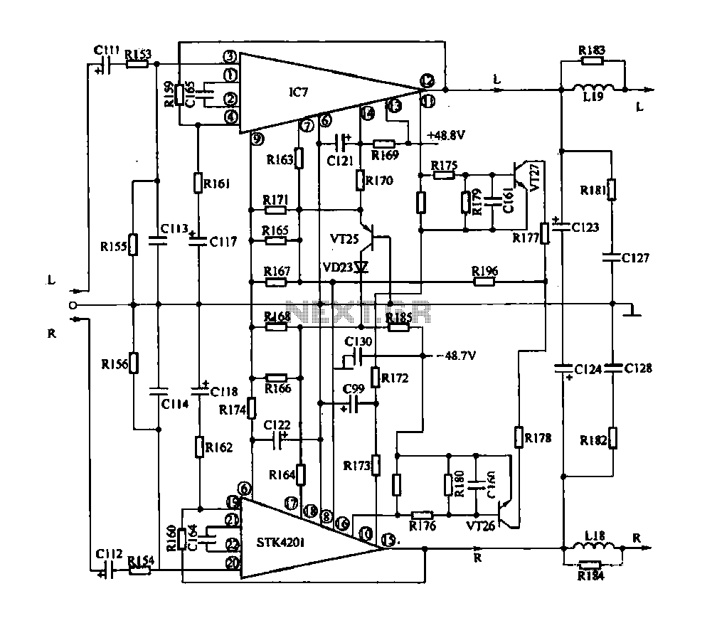
The rapid advancement of integrated circuit technology has led to the widespread emergence of integrated circuit amplifiers. These amplifiers exhibit high levels of technology and performance indicators. Their advantages include compact size, simplified circuitry, exceptional performance, and comprehensive protection...
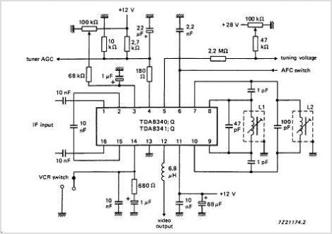
The TDA9813T is an integrated circuit designed for processing vision intermediate frequency (IF) signals and dual frequency modulation (FM) demodulation of sound. It operates with a single reference QSS-IF in television (TV) and video cassette recorder (VCR) applications, specifically...
High Quality unit with LM833 or NE5532 Low noise Dual Op-amp. No need for a preamplifier. Can be directly connected to CD players, tuners and tape recorders. Tested with several headphone models of different impedance: 32, 100, 245, 300,...

This design utilizes a well-established circuit topology for the power amplifier, employing a single-rail supply of approximately 60V and capacitor coupling for the speakers. The advantages of this configuration for a guitar amplifier include a straightforward circuit design, even...
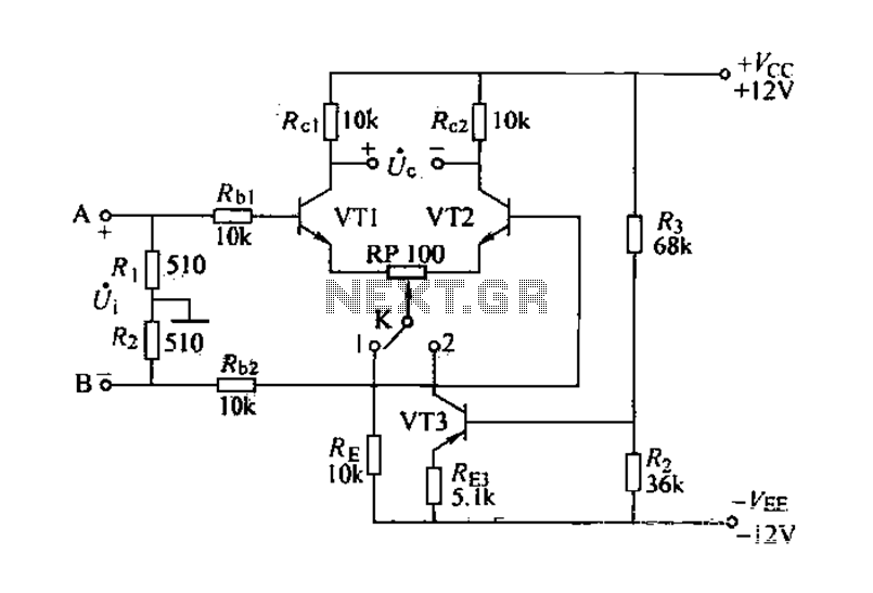
The differential amplifier is known for its stability and zero drift suppression. The circuit, as illustrated, utilizes two identical transistors, VT1 and VT2 (both 3DG6). The reference values for the component parameters are depicted in the figure. The circuit...
This circuit is designed to connect stereo outputs from four different sources or channels as inputs, allowing only one of them to be selected and connected to the output at any given time. When the power supply is turned...
Warning: include(partials/cookie-banner.php): Failed to open stream: Permission denied in /var/www/html/nextgr/view-circuit.php on line 713
Warning: include(): Failed opening 'partials/cookie-banner.php' for inclusion (include_path='.:/usr/share/php') in /var/www/html/nextgr/view-circuit.php on line 713