
60W Power Amplifier with 2N3055
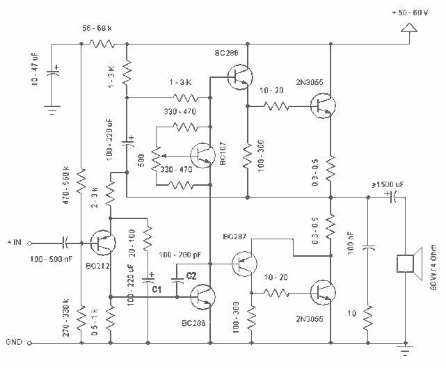
Some comments:
- Capacitor C1 regulates the low frequencies (bass); as the capacitance grows, the low frequencies are getting louder.
- Capacitor C2 regulates the higher frequencies (treble); as the capacitance grows, the higher frequencies are getting quieter.
- This is a class B amplifier, which means that a current must flow through the end transistors, even if there is no signal on the input. This current can be regulated with the 500Ω trimmer resistor. As this current increases, the sound of the amplifier gets better, but the end transistors heat more. Conversely, if this current decreases, the transistors do not heat as much, but the sound quality diminishes.
The described circuit is a basic Class B audio amplifier designed for simplicity and cost-effectiveness. It operates optimally at a supply voltage of approximately 50V, with a permissible range from 30V to 60V, making it versatile for different power supply configurations. The input voltage range is limited to 0.8V to 1V, ensuring compatibility with standard audio signal levels.
The amplifier's architecture allows for the use of various NPN power transistors, excluding Darlington pairs, which may introduce excessive gain and affect linearity. This flexibility in component selection facilitates easier assembly using readily available parts.
Capacitor C1 plays a crucial role in shaping the amplifier's low-frequency response. By increasing its capacitance, the circuit allows more bass frequencies to pass through, enhancing the overall low-end audio output. Conversely, capacitor C2 is responsible for the high-frequency response; increasing its capacitance reduces the treble frequencies, allowing for better control over the amplifier's tonal balance.
The circuit design incorporates a 500Ω trimmer resistor to adjust the bias current flowing through the output transistors. This biasing is essential in Class B amplifiers to minimize crossover distortion, which occurs when the output stage transitions between the two halves of the waveform. Proper adjustment of this bias current can significantly improve sound quality, although it introduces a trade-off regarding thermal management. Higher bias currents enhance audio fidelity but increase the thermal load on the transistors, necessitating adequate heat dissipation measures. Conversely, lower bias currents reduce heat generation but may compromise audio performance.
Overall, this amplifier design exemplifies a balance between performance and component availability, making it an excellent choice for DIY audio enthusiasts.Simple and low cost. The optimal supply voltage is around 50V, but this amp work from 30 to 60V. The maximal input voltage is around 0.8 - 1V. As you can see, in this design the components have a big tolerance, so you can build it almost of the components, which you find at home. The and transistors can be any NPN type power transistor, but do not use Darlington types... The output power is around 60W. Some comments: - capacitor C1 regulates the low frequencies (bass), as the capacitance grows, the low frequncies are getting louder. - capacitor C2 regulates the higher frequencies (treble), as the capacitance grows, the higher frequencies are getting quiter.
- this is a class B amplifier, this means, that a current must flow through the end transistors, even if there is no signal on the input. This current can be regulated with the 500? trimmer resistor. As this current incrases, the sound of the amplifier gets better, but the end transistors are more heating.
But if this current decrases, the transistors are not heating so much, but the sound gets worse... 🔗 External reference
Related Circuits
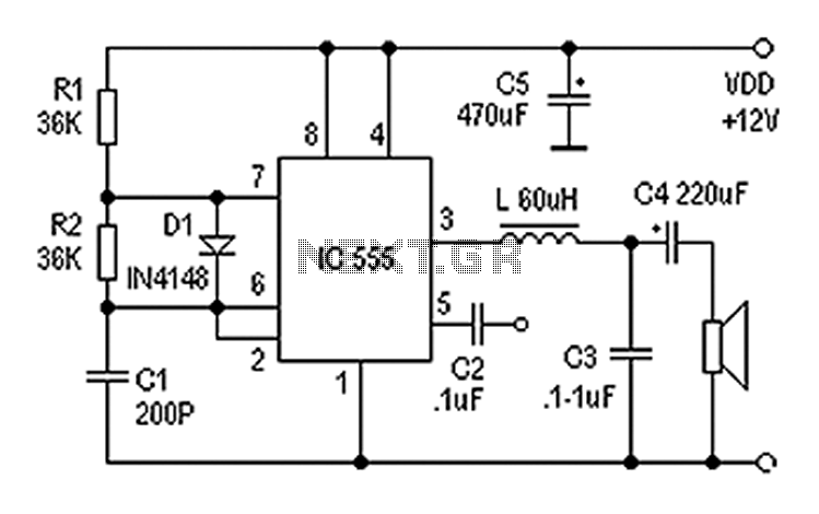
Also known as a digital amplifier, the Class-D amplifier is characterized by its compact size and high efficiency. This circuit utilizes a 555 timer IC to create a Class D amplifier. The 555 timer operates as a controllable multivibrator,...
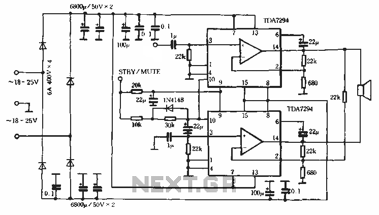
Europe's leading SGS-THOMSON STMicroelectronics recently introduced a new power integrated amplifier, the TDA7294, to the Chinese mainland market. This amplifier, characterized by a cold and hard tone, is particularly suited for Hi-Fi applications such as home theaters and active...
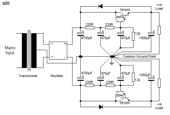
Since I have provided the schematic for John L Linsley-Hood's Class-A amplifier, I felt that some readers may wish to experiment with the concept. Unfortunately, a very low ripple power supply is needed for all Class-A amps, and the...
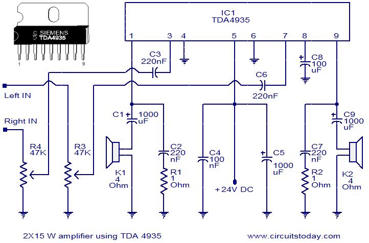
The TDA4935 is a bipolar stereo amplifier integrated circuit (IC) that can be configured as either a 2x15W stereo amplifier or a 30W mono BTL (Bridge-Tied Load) amplifier. This IC includes built-in circuitry for overload protection and over-temperature shutdown....
This page introduces an engaging project designed by Toon Beerten, titled "DIY LED Mood Lamp." This project serves as an intriguing addition to any room, guaranteed to impress viewers. The lamp features a color-fading effect that enhances its visual...
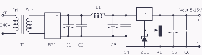
The transformer has a 240V primary and has a secondary rated 24V at 2A. The bridge rectifier contains 4 diodes, their current rating needs to be high with respect to the transformers output current; if not the current may...