
Schematics High Power LED mood Lamp PCB

The DIY LED Mood Lamp project is a sophisticated and visually captivating electronic device that utilizes a microcontroller to control the color output of an RGB LED. The PIC16F628 microcontroller serves as the core component, enabling precise modulation of the LED colors through PWM techniques. PWM allows for the adjustment of the brightness of each color channel (Red, Green, and Blue), resulting in smooth transitions and a wide range of possible colors.
The circuit design incorporates four switches that facilitate user interaction, enabling various operational modes. Each switch is connected to the microcontroller's input pins, allowing the user to select different modes such as color fading, jumping between colors, and setting the speed of transitions. The microcontroller is programmed to interpret these inputs and adjust the PWM signals accordingly.
The choice of housing is critical for achieving the desired aesthetic effect. The diffusion of light through the lamp's housing ensures that colors blend seamlessly, enhancing the overall appearance of the mood lamp. The use of the IKEA Mylonit lamp, with its semi-translucent material, is particularly effective in diffusing light and creating a soft glow.
The high-power 3W RGB LED is capable of producing vibrant colors and is selected for its efficiency and brightness. The LED's performance can be further optimized by selecting appropriate current-limiting resistors, which are essential for protecting the LED from excessive current that could lead to damage.
For assembly, the circuit board can be securely mounted using a hot glue gun, which provides a sturdy and reliable method for placement within the lamp housing. This approach also allows for easy access to the circuit for future modifications or repairs.
Current measurements taken during testing reveal that the maximum current draw of 232 mA is contingent upon the specific LED and resistors utilized in the circuit. Understanding the relationship between current and color output is essential for ensuring the lamp operates within safe limits while achieving the desired visual effects.
Overall, the DIY LED Mood Lamp project exemplifies a blend of creativity and technical skill, offering a rewarding experience for electronics enthusiasts and a stunning visual addition to any space.In this page we will introduce a great project designed by Toon Beerten. His project named "DIY Led Mood Lamp" can become a very interesting add-on for your room that`s absolutely sure it will impress everyone. As you can see on the photos, we talk about a color fading lamp, that looks amazing! The purpose of this page is to try to give some hints building it successful. This high power led mood light is based on PIC16F628 and the ability of this mcu to produce PWM pulses. Varying pulse width we can produce millions of color combinations using only the three basic colors. So only one RGB (Red-Green-Blue) led is capable producing a rainbow of fading colors. With the help of four switches we can handle all functions of the lamp. We can choose fading or jumping between colors, we can select a rainbow style or a random color changing behavior, we can choose slow or fast changing of colors and we can pause on a desired color.
You can use your imagination to find a housing that will be able to diffuse colors uniformly. Color difussion is necessary to achieve best results. In original design the author used the 45cm IKEA Mylonit lamp. That`s a great housing for your lamp. Instead you can use the smaller 31cm IKEA Mylonit lamp with the same amazing results. That`s the lamp we used in our construction. The led used is a high power 3W RGB LED. It can be found on ebay at LEDSEE-electronics. You can also check ebay for other high power RGB leds. It will do the jod the same way. Details of this brilliant led shown below. Programming the PIC16F628 can be achieved using this very simple pic programmer and a program called ic-prog. Just use your programmer and upload the. hex file on your PIC. For successful results you should pay attention on the fuse bits. You should enter the correct fuses as noted on the following table. A good way to mount the circuit board is to use a hot glue gun to "mold" the circuit underneath the lamp housing.
There is plenty of space there for your board. At the next photos you can see the circuit board mounted on the small 31cm IKEA Mylonit Lamp. Finally we have done some current measurements to measure power dissipation. It`s clear that current changes as colors are changing. As you can see the max current needed is 232mA. You should keep in mind that this depends on the led you have and the power resistors you choose. 🔗 External reference
Related Circuits

This varactorless high-frequency modulator electronic project must be powered by a simple DC 3-volt power source, such as a 3-volt battery. Traditionally, high-frequency oscillators are frequency-modulated using a varactor. However, varactors typically require a significant voltage change to achieve...
This line voltage power controller connects a DC control voltage or microprocessor logic output to an AC load. By adding a filter capacitor to the input resistors, the circuit can be controlled by a duty-cycle modulated square wave with...
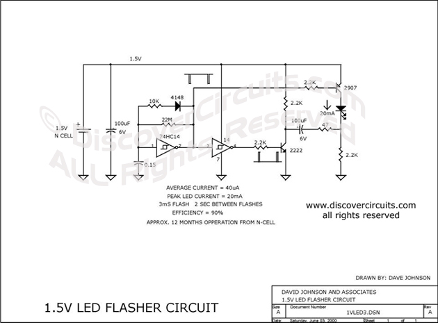
This circuit is designed to extract additional energy from an alkaline battery cell by incorporating two transistors into a configuration similar to a previously mentioned design, thereby enhancing efficiency. A standard 1.5-volt alkaline N cell is capable of powering...
This article describes three options for interfacing the DS1859 to the MAX3735. It includes a new technique using an operational amplifier that provides a linear transfer function, which can be adjusted for any arbitrary current range. All of these...

The EtherSmart Wildcard is based on the Lantronix Xport Ethernet device server, which is integrated into an RJ-45 connector housing. The Xport communicates data through a serial UART-USART interface, while the Wildcard bus operates as a parallel interface. A...
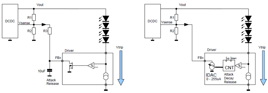
New design techniques in LED driver circuits promise to deliver significant energy savings that will help TV manufacturers meet stringent power consumption requirements. The advancement of LED driver circuits through innovative design techniques has the potential to yield substantial energy...