
6V Gel Cell Battery Charger

This circuit is designed as a 6V Gel Cell Charger, suitable for charging gel cell batteries. It is important to ensure that the charging voltage does not exceed the voltage generated by the solar panel when used in a solar-powered application. The charger is regulated and adjustable, making it compatible with various NiCAD battery configurations, whether single cells or multi-cell arrangements connected in series or parallel. The maximum allowable voltage for the batteries is 18V.
Power transistors Q1 and Q2 function as series regulators, ensuring stable output during the charging process. The circuit also includes an automatic 9V battery charger design, initially developed by Jan Hamer and translated by Tony Van Roon, adhering to European standards. Resistor values in the schematic are specified in ohms, with examples including 120E and 150E.
Additionally, a lead-acid battery charger circuit is included, providing an initial voltage of 2.5V per cell at 25°C to facilitate rapid charging. As the battery charges, the current decreases, and when it drops to 180mA, the charging circuit reduces the output voltage accordingly.
For rechargeable lithium batteries, a charging circuit is designed to deliver a constant current of 60mA for AA cells, with a cutoff voltage of 2.4V per cell to terminate the charge. This system is suitable for multi-cell battery packs consisting of 2 to 6 series-connected cells.
Lastly, the schematic for a 12V NiCAD battery charger is provided, which operates at a charging rate of 200mA per hour. This charger initially delivers 75mA until the battery reaches full charge, after which it switches to a trickle charge to maintain battery health. The circuit is capable of fully recharging a completely depleted battery in approximately 4 hours.This circuit requires a regulated 10V-DC front end capable of supplying 2 Amps. Begins the charge period at 240mA and at full charge switches automatically to a float condition (trickle charge) of 12mA. The capacitors should be the ceramic 50V (or greater) model. Switching transistor T1 is an NPN, Si-Power Output/SW, with a TO-220 case and can be changed by using a appropriate substitute such as the NTE291, ECG291, etc. Timer/Oscillator U1 is a 8-pin NE555V and can be changed with a NTE955M or ECG955M. Resistors R4, R5, R6, and R7 are 1% metal film types. They may not be obtainable at your nearby Radio Shack/Tandy retailer and need to be ordered in. Try Electro-Sonic or Newark Electronics supply stores. Tags: 6V Gel Cell Charger circuit, 6V Gel Cell Charger diagram, Gel Cell Battery, Gel Cell Battery Charger, Gel Cell Battery Charger circuit, Gel Cell Battery Charger schematic, Gel Cell Charger, Gel Cell charger circuit, Gel Cell charger diagram, Gel Cell charger schematic, This is the schematic diagram of solar powered mobile phone battery charger. The circuit is designed to charge the battery from a source with a lower voltage. Do not use it to charge the battery with the same or lower voltage than the voltage which is generated by the solar panel.
For proper operation of. This battery charger circuit is regulated and adjustable to make this circuit able to charge the mosto NiCAD battery. This circuit will work for single cell or multi battery cell which connected with series/parallel connection.
The maximum voltage of the batteries should be 18V maximum. Power transistors Q1 and Q2 are connected as series regulators. This is the diagram of Automatic 9V Battery Charger circuit. The circuit designed by Jan Hamer, translated by Tony Van Roon dan republished in this circuit diagram site. The circuit details are based on european standards. 120E, 150E, etc. The `E` just stands for Ohms so 120 ohm, 150 ohm. The original circuit specified the. The following diagram is the circuit diagram of Lead-Acid battery charger. This circuit provides an initial voltage of 2. 5 V per cell at 25 ƒ to quickly charge the battery. The charging current decreases as the battery is charging, and when the current drops to 180 mA, the charging circuit reduces the output voltage of.
This battery charger circuit is used for rechargable lithium battery. Charging is accomplished with a constant current of 60 mA for AA cells to a cutoff of 2. 4V per cell, at which point the charge must be terminated. The charging system shown is designed for multi-cell battery pack of 2 to 6 series connected cell. The following diagram is the schematic diagram of 12V NiCAD battery charger with charging rate of 200mA/Hour. This NiCAD battery charger circuit charges the battery at 75 mA until the battery is charged, then it reduces the current to a trickle rate.
It will fully recharge a dead/unpowered battery in 4 hours and the battery. 🔗 External reference
Related Circuits
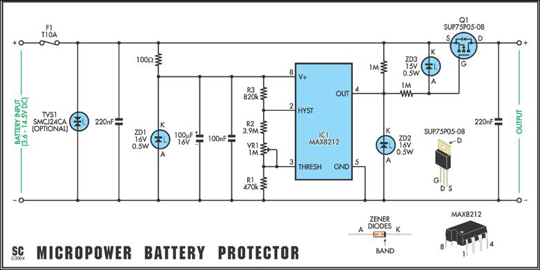
Protect expensive batteries from discharge damage with this mini-sized electronic cutout switch. It uses virtually no power and can be built to suit a wide range of battery voltages. The mini-sized electronic cutout switch serves as a crucial component in...
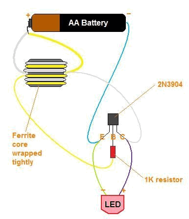
The title contains numerous words because this instructable integrates various concepts from multiple sources. The primary idea originated from Robomaniac's Desktop Energy Seed Lamp, combined with Witch's Growing Plants with LED Lights instructable and various wick gardening planters. The...
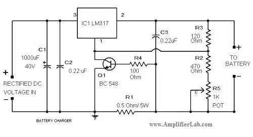
The circuit diagram of a lead-acid battery charger is presented here. The main component of this circuit is the IC LM317. The lead-acid battery charger circuit utilizing the LM317 voltage regulator is designed to efficiently charge lead-acid batteries while providing...
This circuit uses the popular and easy to find LM3914 IC. This IC is very simple to drive, needs no voltage regulators (it has a built-in voltage regulator) and can be powered from almost every source. When the test...
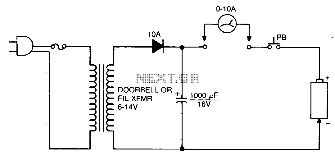
This circuit is designed to eliminate internal shorts in nickel-cadmium batteries. To operate, connect the nickel-cadmium battery to the output and press the pushbutton for three seconds. The circuit functions by utilizing a controlled discharge process to clear internal shorts...
A battery-powered, pushbutton-triggered TTL/CMOS-compatible source of debounced 5V logic pulses is a simple but handy piece of test equipment to have in any tool kit. The circuit's battery-powered operation complicates what would otherwise be a trivial exercise in switch-bounce...