
Car battery tester with LM3914

The LM3914 is a voltage level indicator that can display analog voltage levels in a variety of formats, including bar graph and dot mode. In this application, it is used to monitor the voltage of a car battery, providing a visual representation of the battery's state of charge. The circuit design utilizes a high impedance voltage divider to scale down the car battery voltage from a maximum of 12V to a manageable 1.25V for the IC's internal reference.
When the test button is pressed, the input voltage from the car battery is processed through the voltage divider, which consists of precision resistors. This divider is crucial for ensuring that the voltage fed into the LM3914 does not exceed its maximum allowable input. The internal voltage regulation feature of the LM3914 allows for stable operation without the need for external voltage regulation components, simplifying the overall circuit design.
The output of the voltage divider provides a reference voltage of 1.25V, which corresponds to the maximum input voltage of 12V. The LM3914's internal resistor ladder generates a series of reference voltages, allowing the comparators within the IC to activate the corresponding LEDs in response to the input voltage. The first comparator activates at approximately 0.833V, indicating a low battery voltage of 8V, while the last comparator activates at 1.25V, indicating a fully charged battery at 12V.
The inclusion of a 4700uF smoothing capacitor is an important aspect of this design, particularly in automotive applications where electromagnetic interference (EMI) from the ignition system can introduce noise into the voltage readings. This capacitor helps to filter out such noise, providing a more stable and accurate voltage measurement. Although less critical for diesel engines, it is a precautionary measure for gasoline engines.
Lastly, the flexibility of the LM3914 allows for customization of the output display mode. By disconnecting pin 9 (MODE), the circuit can switch from a bar graph to a dot mode, providing versatility in how the voltage levels are visually represented. This feature caters to user preferences and enhances the usability of the circuit.This circuit uses the popular and easy to find LM3914 IC. This IC is very simple to drive, needs no voltage regulators (it has a built in voltage regulator) and can be powered from almost every source. When the test button is pressed, the Car battery voltage is feed into a high impedance voltage divider.
His purpose is to divide 12V to 1,25V (or lower values to lower values). This solution is better than letting the internal voltage regulator set the 12V sample voltage to be feed into the internal voltage divider simply because it cannot regulate 12V when the voltage drops lower (linear regulators only step down). Simply wiring with no adjust, the regulator provides stable 1,25V which is fed into the precision internal resistor cascade to generate sample voltages for the internal comparators. Anyway the default setting let you to measure voltages between 8 and 12V but you can measure even from 0V to 12V setting the offset trimmer to 0 (but i think that under 9 volt your car would not start).
There is a smoothing capacitor (4700uF 16V) it is used to adsorb EMF noise produced from the ignition coil if you are measuring the battery during the engine working. Diesel engines would not need it, but i'm not sure. If you like more a point graph rather than a bar graph simply disconnect pin 9 on the IC (MODE) from power.
For the first comparator the voltage is : 0,833 V corresponding to 8 V. for the last comparator the voltage is : 1,25 V corresponding to 12 V. 🔗 External reference
Related Circuits
The circuit is actually a half-wave rectifier. It only charges the battery on every half cycle. The plug pack doesn't like this as it leaves residual flux in the core of the transformer and causes it to overheat. But...
A common car inverter circuit and its working principle. Car inverter specifications include: Input voltage: DC 10V to 14.5V; Output voltage: AC 200V to 220V with a tolerance of 10%; Output frequency: 50Hz with a tolerance of 5%; Output...
The DS2715 is a comprehensive NiMH (Nickel Metal Hydride) smart charger solution featuring load detection, making it ideal for cost-effective applications. The DS2715 smart charger integrates several key functionalities designed to enhance the charging process for NiMH batteries. It employs...

This circuit is designed to charge between one and twelve NiCd cells using a car battery. With switch S1 set to the normal position, it is capable of charging up to six cells. The circuit operates by utilizing a car...
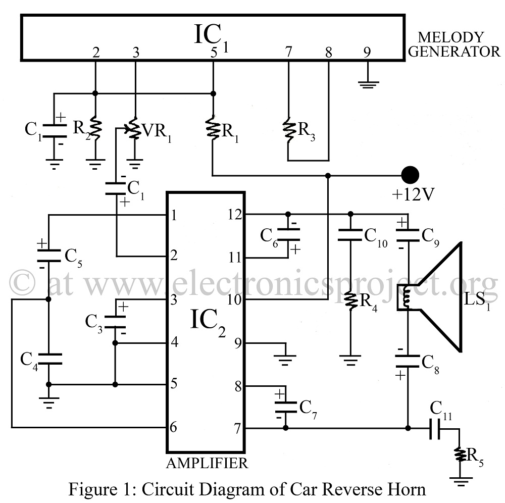
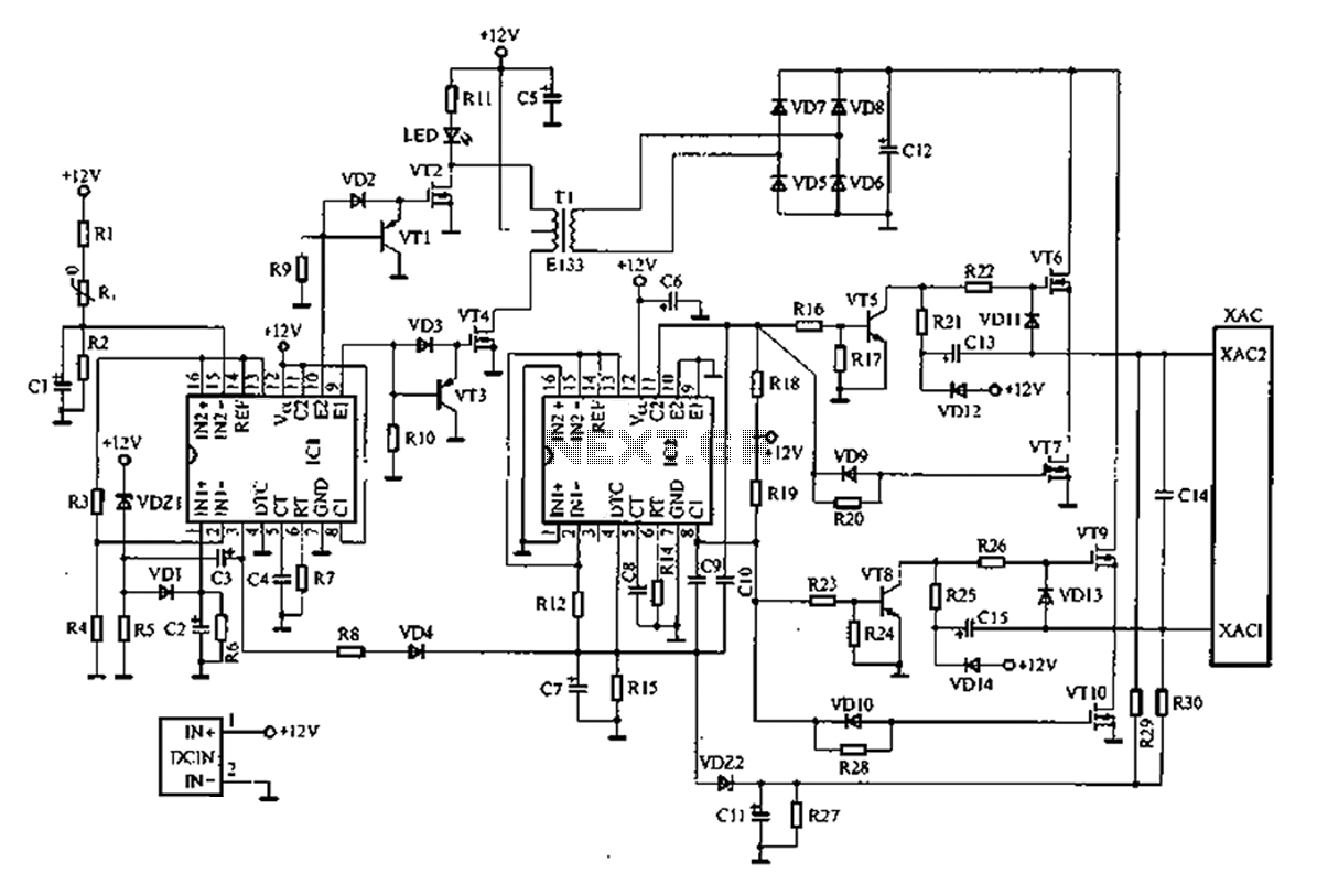
The Car Reverse Horn is a circuit designed for use in vehicles, utilizing a melody generator integrated circuit (IC) CTC2877 in conjunction with an amplifier IC AN7148. This circuit diagram facilitates the implementation of a reverse horn system in...
This indicator shows through a dual-LED see if a fuse is intact. The module is designed for 230 V AC. The green LED illuminates when the fuse is still good, the red lights when the fuse is broken. Perhaps...