
6v to 12v converter circuits
The 6V to 12V DC converter circuit operates on the principle of boosting the input voltage through a switching mechanism. The LM2577-ADJ voltage regulator is a key component, functioning as a step-up converter that utilizes an inductor to store energy and release it at a higher voltage. The 555 timer IC, working in astable mode, generates a square wave signal that controls the TIP41C transistor, allowing it to switch on and off rapidly. This switching action creates a pulsed current through the inductor, which, when combined with the output capacitor, results in a higher average output voltage.
The circuit design includes a feedback mechanism to maintain the desired output voltage. The zener diode provides a reference voltage that stabilizes the output by shunting excess voltage to ground, ensuring that the output voltage remains consistent even under varying load conditions. The use of a 1000uF capacitor is critical for filtering out voltage ripples, resulting in a smooth DC output suitable for sensitive electronic devices.
The efficiency of approximately 75% indicates that while some power is lost as heat, the design remains effective for applications where moderate current is required. The simplicity of the circuit, along with the readily available components, makes it an attractive option for hobbyists and engineers looking to power 12V devices from a 6V source. Overall, this circuit exemplifies a practical solution for voltage conversion in automotive and portable applications.6V to 12V DC converter circuits that can be used to convert a small voltage of about 6 volts to a higher voltage of 12 volts but ofcourse with a lower current rating. This inverter circuit can provide up to 800mA of 12V power from a 6V supply. For example, you could run 12V car accessories in a 6V car. The circuit is simple, about 75% efficient and quite useful. By changing just a few components, you can also modify it for different voltages. The cost of building the 6volts to 12 volts converter should be low enough to justify constructing it instead of modifying the entire equipment setup to work directly with a 6 volts power supply. The two principles of simplicity and functions properly without the need of the transformer. This is a Simple Switcher step-up voltage regulator made by National Semiconductor, (part number LM2577-ADJ).
Together with a few extra components, a heat sink and some wiring, it is possible to generate over 1A from the battery of an Austin. The output connector is taken from a car charger extension lead, so that a phone or a sat-nav just plugs straight in.
This 6V to 12V dc-dc boost converter can drive a load in 12V about 3A current. The 555 timer IC is operated in astable mode, generates about 29Khz frequency of about 54% duty cycle drives the input of TIP41C transistor. 1000uF capacitor smoothens the output voltage of the dc-dc converter. LED and 1. 5Kohm resistor serves as indicator and load for output stability when no load is connected. You can add a 12V zener diode (1N5242B)across output to ground for further output stability. 🔗 External reference
Related Circuits
As the demand for VRM output current increases, the components and parts of the SR-Buck converter can no longer meet the requirements for the new generation microprocessors needing 100 A. Additionally, creating filtering inductance for high currents is quite...
The circuits in Figure 1 and Figure 2 demonstrate specific advantages over the circuit presented in the Design Idea in EDN, titled "Circuit detects first event," published on May 3, 2001, page 89. The n-player first-event detection circuit provides...
This circuit facilitates a VGA to SCART connection, converting VGA signals into RGB and composite sync signals suitable for a TV via a SCART connector. The RGB components—Red, Green, and Blue—output from the VGA card are already at the...
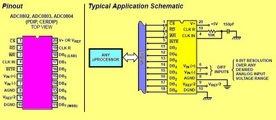
The circuit involves 8-bit, microprocessor-compatible analog-to-digital converters (A/D converters). It utilizes the ADC0804 chip for converting analog signals to digital form, in conjunction with an AT89C2051 microcontroller. The ADC0802 family consists of CMOS 8-bit, successive-approximation A/D converters that employ...
A computerized infrared remote project is a simple device designed for recording and playing back streams of infrared data, specifically the codes transmitted by remote controls. Software is provided for use in both DOS and Windows environments, along with...
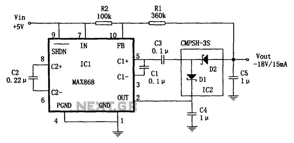
The circuit utilizes the IC1 MAX868 and CMPSH-3S to create a quadruple voltage DC/DC converter power supply. The IC1 MAX868 is an inverting charge pump regulator integrated circuit that can generate an output voltage of up to -2VIN, with...