
6volt gel cell charger
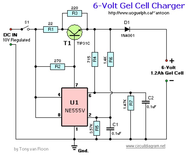
This circuit design is intended for applications requiring a reliable and efficient charging system. The primary component, a 10V DC power supply, must be capable of providing a steady output of 2 Amps to ensure adequate charging current. The circuit begins charging at a rate of 240mA, which is suitable for initial battery acceptance. Once the battery reaches full charge, the circuit intelligently transitions to a trickle charge mode, reducing the current to 12mA to maintain the battery without overcharging.
The use of capacitors rated for at least 50V is crucial for ensuring the circuit's reliability and longevity, especially under varying load conditions. The choice of the NPN transistor Q1, with its TO-220 package, allows for efficient heat dissipation and robust performance under continuous operation. Alternatives such as the NTE291 and ECG291 provide flexibility in sourcing components while maintaining circuit functionality.
Resistors R4, R5, R6, and R7 are specified as 1% metal film types to ensure precision in the circuit's performance. These resistors play a vital role in setting the charging current and ensuring proper operation of the transistor switch. As these components may not be readily available in all retail outlets, sourcing them from specialized electronic component distributors like Electro-Sonic or Newark Electronics is recommended.
Overall, this circuit design is well-suited for applications that require a precise charging mechanism, with built-in safeguards to prevent overcharging and ensure optimal battery maintenance. Proper selection and sourcing of components are essential for achieving the desired performance and reliability in the charging process.This Circuit needs a adapted 10V-DC advanced end able of bartering 2 Amps. Starts the allegation aeon at 240mA and at abounding allegation switches automatically to a float action (trickle charge) of 12mA. The capacitors are the bowl 50V (or better) type. Switching transistor Q1 is a NPN, Si-Power Output/SW, with a TO-220 case and can be replaced with a acceptable acting like the NTE291, ECG291, etc. Resistors R4, R5, R6, and R7 are 1% metal blur types. They may not be accessible at your bounded Radio Shack/Tandy abundance and accept to be ordered in. Try Electro-Sonic or Newark Electronics accumulation stores. 🔗 External reference
Related Circuits
Disconnecting the alarm system from the horn relay will eliminate the horn's sound during an actual alarm. This circuit silences the arming beep while maintaining the alarm by introducing a small delay into the signal. It is positioned between...
This is a dry cell battery charger circuit designed to charge batteries over a period of approximately 12 hours. When powered by a 9-volt supply, the circuit is configured to accommodate AA-sized batteries. If C or D-sized batteries are...
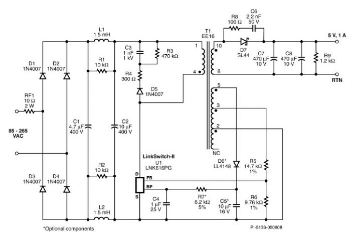
A very simple 5-volt constant voltage, constant current (CV/CC) universal-input power supply for cell phone or similar charger applications can be designed using the LNK616PG product from the LinkSwitch-II family. This low-cost charger adapter accepts a wide range of...
This device is designed to be a simple, inexpensive comparator intended for use in a solar cell power supply setup where a quick indication of "too low" or "just right" voltage is needed. The circuit consists of one 5V...
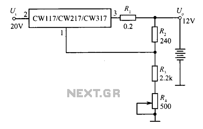
A 12V constant voltage charger is depicted. The power supply circuit shares the same basic design. The resistor R1, valued at 0.2 ohms, serves a limiting function, effectively increasing the internal resistance of the charger, which in turn reduces...

This is a simple and low-cost NiCd and NiMH battery charger. The schematic diagram indicates that the charging current (I) should be set to 1/10 of the battery's rated capacity. For instance, if the battery has a rated capacity...
Warning: include(partials/cookie-banner.php): Failed to open stream: Permission denied in /var/www/html/nextgr/view-circuit.php on line 713
Warning: include(): Failed opening 'partials/cookie-banner.php' for inclusion (include_path='.:/usr/share/php') in /var/www/html/nextgr/view-circuit.php on line 713