
Solar Cell Voltage Regulator circuit

The described comparator circuit serves as a voltage monitoring tool in solar power applications. The primary function is to provide visual feedback regarding the voltage level of the power supply, ensuring that the output voltage remains within acceptable limits.
The circuit architecture includes a 5V voltage regulator that stabilizes the output voltage for the transistors, ensuring consistent operation. The two transistors are configured as switches, which control the operation of the two LEDs based on the input voltage level. When the voltage falls below a predetermined threshold, one of the LEDs will illuminate, signaling that the voltage is "too low." Conversely, when the voltage is within the acceptable range, the second LED will light up, indicating that the voltage is "just right."
The five resistors in the circuit play crucial roles in setting the biasing conditions for the transistors and determining the voltage thresholds for the LED indicators. Resistors are also used to limit the current flowing through the LEDs, preventing damage and ensuring longevity. The two capacitors serve to filter any voltage spikes or noise in the power supply, contributing to the stability of the circuit's operation.
The choice of battery is flexible, allowing for various configurations depending on the user's needs. The circuit can effectively operate with a 4V battery, or alternatives such as 4.5V from three alkaline batteries or 3.6V from three NiCd cells, making it versatile for different solar power setups.
Overall, this simple comparator circuit is an efficient and cost-effective solution for monitoring voltage levels in solar cell power supply systems, providing clear visual indicators for users.This device is designed to be a simple, inexpensive ˜comparator, intended for use in a solar cell power supply setup where a quick ˜too low or ˜just right voltage indicator is needed. The circuit consists only of one 5V regulator, two transistors, two LEDs, five resistors, two capacitors, and one small battery.
Although a 4-V battery is indicated, 4.5 V (3 alkalines in series) or 3.6 V (3 NiCd cells in series) will also work.. 🔗 External reference
Related Circuits
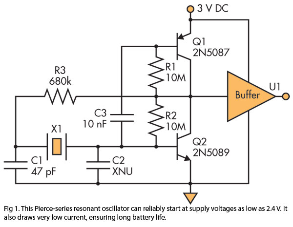
A Pierce (crystal) oscillator designed to deliver a stable clock signal for a minimum duration of one year when powered by battery voltages as low as 2.4 V. The Pierce oscillator circuit is a type of crystal oscillator that utilizes...
The total gain of the car antenna amplifier is approximately 30 dB, with an input impedance of around 10 kΩ at 30 MHz. The amplifier should be mounted directly at the base of the antenna to prevent signal losses...
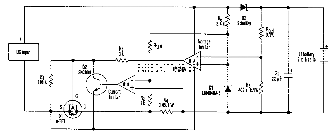
A universal rechargeable lithium battery circuit design, applicable to different battery types and numbers of batteries. This is because both the charger output voltage or current limit setpoint and the maximum charging current can be adjusted by simply changing...
The LED arrangement in the LM339 circuit consists of two rows of three LEDs, with each LED connected in parallel. The two rows are connected in parallel but with reversed polarity. The sensor array is composed of three west-facing...
For example, I do not understand the process of demodulation or the modulation itself, and so on. Is there someone who can understand this circuit? Could you please assist me? The circuit in question likely involves a modulation and demodulation...
This 5-volt Switch Mode Power Supply circuit utilizes an integrated circuit (IC) from National Semiconductor, which specializes in the production and design of ICs for switch-mode power supply applications. The 5-volt Switch Mode Power Supply (SMPS) circuit is designed to...