
7 segment Display
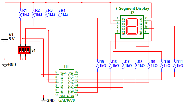
The multiplexed 7-segment display PCB is designed for efficient visual representation of numerical data. Each MAN72 7-segment display is a common-anode type, meaning that the anode connections of all segments are tied together to a common voltage source, while individual cathodes are connected to digital control signals. This configuration allows for the multiplexing of multiple displays, enabling the control of several digits with fewer I/O pins from a microcontroller.
In this setup, the PCB likely incorporates a microcontroller or a dedicated display driver IC that manages the timing and control signals to each segment. The multiplexing technique involves rapidly switching the display outputs, illuminating one display at a time in quick succession. This creates the illusion of all displays being lit simultaneously due to the persistence of vision effect.
The design of the PCB would include appropriate resistors for current limiting on each segment to protect the LEDs from excessive current. Additionally, decoupling capacitors may be placed near the power supply pins of the display driver to ensure stable operation, and the layout would be optimized for minimal trace lengths to reduce signal degradation.
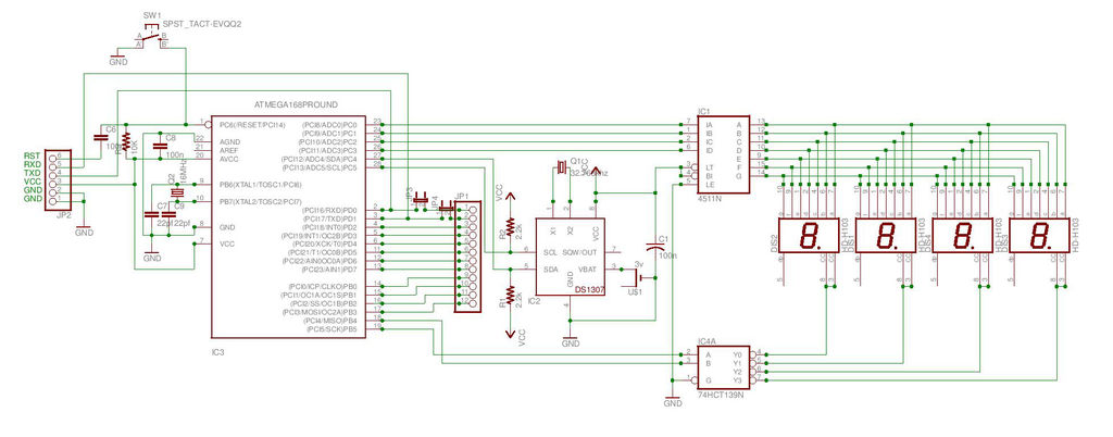
The overall configuration enables applications in various electronic devices where numerical output is required, such as clocks, counters, and measurement instruments, providing a cost-effective and space-efficient solution for displaying numerical information.Multiplexed 7-Segment Display PCB The display PCB consists of four MAN72 7-segment common-anode .. 🔗 External reference
Related Circuits
This is the second instructable focused on creating a digital watch as a learning experience. An Atmega644 chip from a Sanguino was available, which would have sufficed, but the intention was to burn an Arduino bootloader and test its...
The circuit was designed to create a low-cost frequency meter that will cover the range of 1 Hz to 1 MHz with a digital indication using three 7-segment displays. The frequency meter circuit operates by measuring the frequency of an...

The programmed Signetics 8223 256-bit PROM is utilized as an alphanumeric display featuring five 7-segment digits, which are interconnected to simulate abbreviations for units of measurement such as seconds, milliseconds, microseconds, hertz, kilohertz, and megahertz, represented as SEC, SEC-3,...
Alternative display methods exist beyond the original 8 LED frequency counter, potentially offering improved readability and a more suitable format for QRP equipment. This document presents examples of binary decimal displays. Typically, the counter omits the MHz position, focusing...
The Over-the-Top type of operational amplifier is ideal for use as a current sense for battery charger applications. The design described here can be used. The Over-the-Top operational amplifier (op-amp) is specifically designed for applications requiring precise current sensing, particularly...

The 040904C version of the code has a larger UART receive buffer and supports two pushbuttons that send either an ASCII "R" ($52) or an ASCII carriage. Something to keep in mind when using AVR controllers that support 16-bit...