
1Hz to 1MHz Frequency Meter with Digital Display

The frequency meter circuit operates by measuring the frequency of an input signal and displaying the result on three 7-segment displays, which provide a clear digital readout. The design incorporates a microcontroller or a frequency counter IC to process the input signal and convert it into a frequency value.
The input signal is typically fed into a conditioning circuit that may include a buffer and a filter to ensure that the signal is clean and within the acceptable voltage levels for the measuring device. The frequency counter then counts the number of cycles of the input signal over a specified time interval, which can be adjusted based on the required accuracy and resolution.
To achieve a frequency range of 1 Hz to 1 MHz, the circuit may employ a combination of a prescaler and a timer. The prescaler divides the input frequency by a predetermined factor, allowing the frequency counter to handle higher frequencies without exceeding its maximum counting capability. The timer controls the measurement period, ensuring that the counting is accurate and stable.
The output from the frequency counter is then processed and sent to the three 7-segment displays. Each display is driven by a suitable driver circuit, which translates the binary output from the frequency counter into the corresponding decimal digits that can be displayed. The use of three 7-segment displays allows for the representation of frequencies in a format that is easy to read, accommodating values from 000 Hz to 999 kHz.
Power supply considerations are also essential, with the circuit typically requiring a stable voltage source to ensure accurate measurements. In addition, proper grounding and layout design are crucial to minimize noise and interference, which could adversely affect the frequency readings.
Overall, this low-cost frequency meter design is suitable for various applications, including educational purposes, hobby projects, and basic frequency measurement tasks in laboratory settings.The circuit was designed to create a low cost frequency meter that will cover the range of 1 Hz to 1 MHz with a digital indication using three 7-segment d. 🔗 External reference
Related Circuits
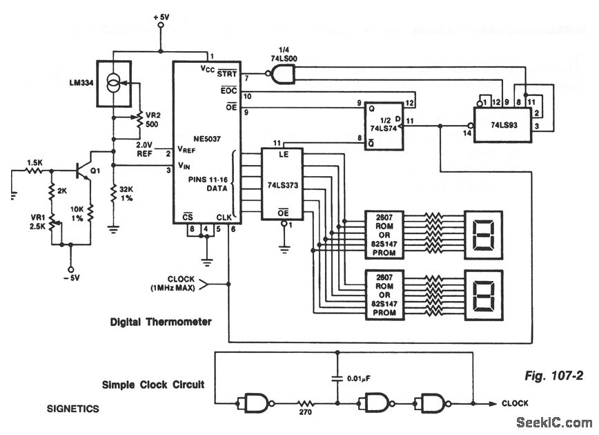
The ROMs or PROMs must contain the correct code for converting data from the NE5037, which serves as the address for the ROMs or PROMs, into the appropriate segment driver codes. The displayed temperature can be converted to degrees...
The LM3915 is a monolithic integrated circuit that senses analog voltage levels and drives ten LEDs providing a logarithmic 3 dB/step analog display. LED current drive is regulated and programmable, eliminating the need for current limiting resistors. More: This...
The circuit was designed to create an electronic oscillator known as the Wien Bridge Oscillator, which can be used for the generation of low-frequency sine waves. The Wien Bridge Oscillator is a type of electronic oscillator that generates sine waves....
Currently, high-power, high-frequency, narrow pulsing applications primarily utilize vacuum tubes, such as secondary electron transmitting tubes, discharge gap switches, trigatrons, and hydrogen brake pipes. The main research focus is on improving the switching speed of these vacuum devices, aiming...
A high-input-resistance op-amp, a bridge rectifier, a microammeter, and a few other discrete components are all that are required to realise this versatile circuit. This circuit can be used for measurement of dc, ac rms, ac peak, or ac...
Superheterodyne receivers have been mass-produced since around 1924, but for reasons of cost did not become successful until the 1930s. Before World War II, other, simpler receiver technologies such as the TRF receiver and the regenerative receiver were still...