
7-Segment Displays

The DE2 Board is equipped with eight 7-segment displays, strategically organized into two pairs and one group of four, facilitating the representation of numerical data in multiple formats. The displays are driven by a Cyclone II FPGA, which manages the illumination of each segment through its pin configuration. The schematic representation in Figure 1 illustrates the connections between the FPGA pins and the segments of the displays.
Each of the seven segments within a 7-segment display is controlled individually. When a low logic level (typically 0 volts) is applied to a segment, it activates, causing that segment to emit light. Conversely, applying a high logic level (usually 3.3 volts) deactivates the segment, turning it off. This binary control allows for precise manipulation of the displayed numbers.
The segments are indexed from 0 to 6, corresponding to the standard layout of a 7-segment display, as depicted in Figure 2. This indexing system enables easy reference and programming for the FPGA to control which segments are lit at any given time. It is important to note that the dot segment, often used for decimal points, remains unconnected in this configuration and is not available for use.
To facilitate the interfacing between the FPGA and the displays, Table 1 provides a detailed mapping of the FPGA pin assignments to each segment of the 7-segment displays. This mapping is crucial for ensuring that the correct signals are sent to the respective segments, allowing for accurate numerical representation on the displays. The careful design and integration of these components on the DE2 Board exemplify effective engineering practices in digital display technology.The DE2 Board has eight 7-segment displays. These displays are arranged into two pairs and a group of four, with the intent of displaying numbers of various sizes. As indicated in the schematic in Figure 1, the seven segments are connected to pins on the Cyclone II FPGA.
Applying a low logic level to a segment causes it to light up, and applying a high logic level turns it off. Each segment in a display is identified by an index from 0 to 6, with the positions given in Figure 2. Note that the dot in each display is unconnected and cannot be used. Table 1 shows the assignments of FPGA pins to the 7-segment displays. 🔗 External reference
Related Circuits
This project aims to develop expertise in using seven-segment displays in various applications. The system will be designed to display any integer from 0 to 9999 using four seven-segment displays. A function named Print() will be created to facilitate...
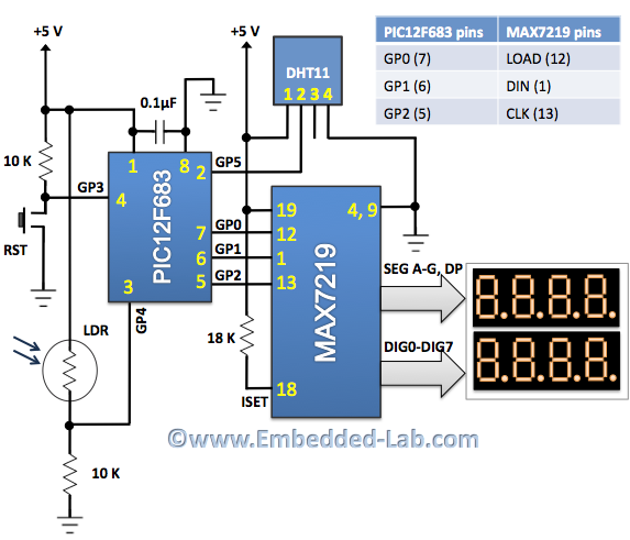
An automatic brightness adjustment is a closed-loop system that has the capability to assess ambient light and adjust the brightness of the display accordingly. The automatic brightness adjustment circuit operates by utilizing a light sensor, typically a photoresistor (LDR) or...
The 7-segment LED display is a highly useful component, yet it can be quite confusing and challenging for beginners to use. However, it becomes straightforward once it is operational for the first time. The display consists of seven LEDs,...
LED displays consist of arrays of Light Emitting Diodes (LEDs) arranged in various shapes to convey specific information. The operation of LED displays is similar to that of standard LEDs, requiring straightforward connections when sufficient microcontroller pins are available....
A brief history: Like many tutorials, this one begins with a historical overview. However, it must be noted that there is limited background information available regarding the development of 7-segment displays. 7-segment displays are widely used electronic components that...
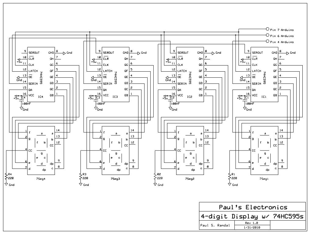
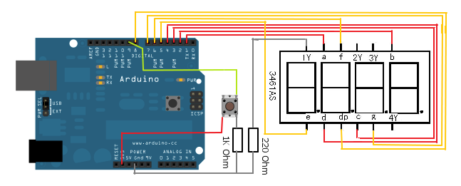
Four 595 shift registers are used together to drive 7-segment displays, with additional code implemented to accept input from a PC. Unlike the previous design that utilized 10-LED bar graphs, the current configuration employs 7-segment displays, which present a...