
Multiplexed Seven Segment Displays - Part II
The program is structured to showcase the use of seven-segment displays in multiplexed mode. It includes the necessary libraries and defines the ports for the displays. The main components of the program are as follows:
1. **SevenSegment Function**: This function takes a digit and a decimal point indicator as inputs. It writes the corresponding binary value to the display port based on the digit provided. If the digit exceeds 9, an error indication is displayed.
2. **Wait Function**: This function introduces a delay in the program, allowing time for the display to update.
3. **Print Function**: This function takes a 16-bit integer, breaks it down into its individual digits, and stores them in an array. If the number exceeds 9999, the function exits without processing.
4. **Main Function**: This is the core of the program, where the timer is configured and the displays are initialized. It enters an infinite loop that calls the Print() function to display numbers from 0 to 9999, with a delay between each update.
5. **Interrupt Service Routine (ISR)**: This routine is triggered by a timer overflow and is responsible for updating the displays. It cycles through the displays, activating one at a time and writing the corresponding digit to it.
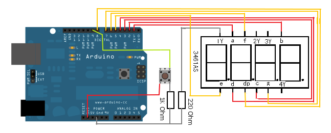
The project utilizes AVR microcontroller programming, specifically leveraging the AVR I/O library for direct port manipulation. The seven-segment display is controlled through a multiplexing technique, which allows multiple displays to be controlled with fewer I/O pins. Each display is activated in succession, ensuring that only one display is illuminated at any given time, which creates the illusion of all displays being active simultaneously.
This project serves as an excellent introduction to working with seven-segment displays, providing foundational knowledge that can be applied to more complex electronic systems. The ability to reuse the Print() function in future projects enhances efficiency and reduces development time.A small project that will make you expert in using these displays in your own projects. We will make a system that can display any number between 0-9999 using four of these displays. We will design a function Print() that we can use on latter projects to easily write integers onto displays. Once we have successfully tested this function we can add to to any project without any problem. This concept of code reuse will make bigger project both easy to make and far less painful. In this sample project we will test our function by using it in a loop to print all numbers from 0-9999. /* Program to demonstrate the use of Seven Segment Displays In Multiplexed Mode. _ Author: Avinash Gupta Date: 11 Oct 08 Updated: Web: */ #include
gfedcba SEVEN_SEGMENT_PORT=0b00111111; break; case 1: //. gfedcba SEVEN_SEGMENT_PORT=0b00000110; break; case 2: //. gfedcba SEVEN_SEGMENT_PORT=0b01011011; break; case 3: //. gfedcba SEVEN_SEGMENT_PORT=0b01001111; break; case 4: //. gfedcba SEVEN_SEGMENT_PORT=0b01100110; break; case 5: //. gfedcba SEVEN_SEGMENT_PORT=0b01101101; break; case 6: //. gfedcba SEVEN_SEGMENT_PORT=0b01111101; break; case 7: //. gfedcba SEVEN_SEGMENT_PORT=0b00000111; break; case 8: //. gfedcba SEVEN_SEGMENT_PORT=0b01111111; break; case 9: //. gfedcba SEVEN_SEGMENT_PORT=0b01101111; break; } if(dp) { //if decimal point should be displayed //make 7th bit high SEVEN_SEGMENT_PORT|=0b10000000; } } else { //This symbol on display tells that n was greater than 9 //so display can`t handle it SEVEN_SEGMENT_PORT=0b11111101; } } void Wait() { uint8_t i; for(i=0;i<10;i+) { _delay_loop_2(0); } } void Print(uint16_t num) { /* This function breaks apart a given integer into separate digits and writes them to the display array i. e. digits[] */ uint8_t i=0; uint8_t j; if(num>9999) return; while(num) { digits[i]=num%10; i+; num=num/10; } for(j=i;j<4;j+) digits[j]=0; } void main() { uint16_t i; // Prescaler = FCPU/1024 TCCR0|=(1<
i=0; } else { //Goto Next display i+; } //Activate a display according to i PORTB&=(0b11110000); PORTB|=(1<
Related Circuits
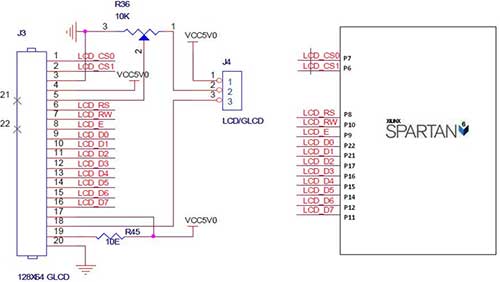
The Spartan-6 board features a 2x16 LCD, as illustrated in the accompanying figure. This 2x16 character LCD interface card supports both 4-bit and 8-bit modes, and it includes a facility for contrast adjustment via a trim potentiometer. In the...
Most blog posts involve short 3-4 hour projects or hacks that are built for learning and enjoyment. It was time to develop something more substantial. The project described appears to focus on creating electronic circuits that can be completed within...
The objective of this lab is to create a decimal counter that counts from 0 to 99 using the 80X51 microcontroller. A C program must be written for this purpose, which will then be compiled using the C51 compiler...
7-Segment Common LED UV Exposure Box Circuit Diagram. Features: Utilizes Stan Ocker's circuit design, employing a PIC16F84 microcontroller to count and display the time. The 7-Segment Common LED UV Exposure Box Circuit is designed for applications requiring precise timing and...
The 7-segment LED display is a highly useful component, yet it can be quite confusing and challenging for beginners to use. However, it becomes straightforward once it is operational for the first time. The display consists of seven LEDs,...
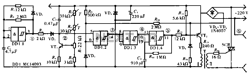
The circuit operates using a temperature stabilizer derived from the main oscillator (DD1.1), along with components including C1, R1, R2, and VD1. It incorporates a monostable multivibrator formed by R3, VD2, VT1, C2, R4, DD1.2, R7, and R8, as...
Warning: include(partials/cookie-banner.php): Failed to open stream: Permission denied in /var/www/html/nextgr/view-circuit.php on line 713
Warning: include(): Failed opening 'partials/cookie-banner.php' for inclusion (include_path='.:/usr/share/php') in /var/www/html/nextgr/view-circuit.php on line 713