
7 segment LED display driver
More: It's inexpensive, and there's an open-source IDE for programming. Works great, but one issue that I quickly ran into was remembering my circuits. I'd make something up on a breadboard, write a program for it, and then tear it apart to build another circuit. When I wanted to go back to an earlier circuit, I had the program saved, but I couldn't always remember how I had wired up the circuit.
So I went looking for a program that would let me document my circuits, and I found Fritzing. It's very easy to use. You drag parts off a palette and connect them up with drag and drop. You can work on a breadboard view or a schematic view, and they are automatically kept in sync. You can easily put bends into wires to route them in more visually appealing ways.
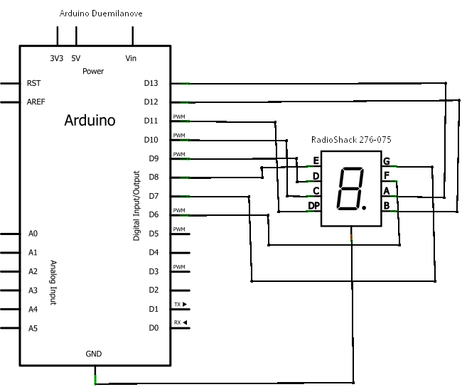
Here's an example of a circuit using the Arduino Duemilanove and a 7 Segment Red LED 0.3" Digital Display (RadioShack 276-075).
Building this I was able to experiment with another feature of Fritzing, because the 7 Segment LED included in the core parts of the tool was a common anode numerical display. Although these pictures don't show anode/cathode on the pins, it is visible in the tool, and I wanted to get it right. So I edited the part, changed the pin wiring, and saved it as a new part. This was all very straightforward.
Then I decided I wanted to have the pins be labeled A, B, C so that it would show up in the schematic view. All the images are SVG, and I didn't have an SVG editor handy, so I used svg-edit, an online browser-based editor. I copied the "7-segment display.svg", added the letters, saved it into a new svg file, and selected it within Fritzing. I did need to close and reopen Fritzing for it to refresh the schematic which already had the old image on it, but I didn't need to remove and re-add.
The Arduino platform is a versatile tool for electronic prototyping, offering a microcontroller with a range of digital and analog input/output pins. The Arduino Duemilanove, specifically, is compatible with various components, including a 7-segment LED display. This display is typically used to show numerical information in a clear and concise manner.
In a typical setup, the common anode configuration of the 7-segment display means that the anode (positive terminal) of the LEDs is connected to the power supply, while the cathodes (negative terminals) are connected through resistors to the Arduino's digital pins. Each segment of the display can be turned on or off by controlling the corresponding pin, allowing for the display of numbers from 0 to 9.
Fritzing enhances the design process by allowing users to create a visual representation of their circuits. The breadboard view provides a realistic layout of components, while the schematic view offers a more abstract representation of the connections. This dual-view capability ensures consistency and helps in documenting the circuit effectively.
Modifications to components, such as editing the pin configuration of the 7-segment display, can be accomplished easily within Fritzing. Users can create custom parts tailored to their specific needs, which is particularly useful for ensuring correct wiring and functionality in projects. The use of SVG files for graphics allows for easy customization and labeling, enhancing the clarity of the schematic representation.
In summary, the combination of the Arduino Duemilanove and the 7-segment display provides a practical example of how to utilize Fritzing for electronic circuit design. The ability to edit and customize parts, along with the seamless integration of schematic and breadboard views, makes Fritzing an invaluable tool for both novice and experienced electronics enthusiasts.If you're not familiar with the Arduino, it is "an open-source electronics prototyping platform based on flexible, easy-to-use hardware and software". It has a small microcontroller, a USB port to connect to your computer for programming, a power socket for providing power when the USB cable isn't connected, and various digital and analog input and output pins, for connecting up to leds, switches and various sensors.
It's inexpensive, and there's an open source IDE for programming. Works great, but one issue that I quickly ran into was remembering my circuits. I'd make something up on a breadboard, write a program for it, and then tear it apart to build another circuit. When I wanted to go back to an earlier circuit, I had the program saved, but I couldn't always remember how I had wired up the circuit.
So I went looking for a program that would let me document my circuits, and I found Fritzing. It's very easy to use. You drag parts off a palette and connect them up with drag and drop. You can work on a breadboard view or a schematic view, and they are automatically kept in sync. You can easily put bends into wires to route them in more visually appealing ways. Here's an example of a circuit using the Arduino Duemilanove and a 7 Segment Red LED 0.3" Digital Display (RadioShack 276-075). Building this I was able to experiment with another feature of Fritzing, because the 7 Segment LED included in the core parts of the tool was a common anode numerical display.
Although these pictures don't show anode/cathode on the pins, it is visible in the tool, and I wanted to get it right. So I edited the part, changed the pin wiring, and saved it as a new part. This was all very straightforward. Then I decided I wanted to have the pins be labeled A, B, C so that it would show up in the schematic view.
All the images are SVG, and I didn't have an SVG editor handy, so I used svg-edit, an online browser based editor. I copied the "7-segment display.svg", added the letters, saved it into a new svg file, and selected it within fritzing.
I did need to close and reopen Fritzing for it to refresh the schematic which already had the old image on it, but I didn't need to remove and re-add. 🔗 External reference
Related Circuits

Function generators are essential in the design, testing, and operation of encoders, modulators, demodulators, and measurement instruments. This document presents an economical method to construct a bus-controlled sinewave oscillator that exhibits exceptionally low distortion. The circuit produces a sinusoidal...
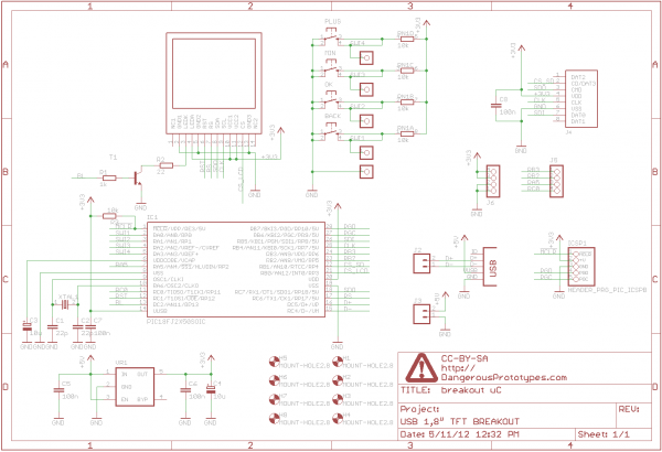
A 1.8" TFT display was sourced from China, and a breakout board was designed for it. This version not only breaks out the pins but also includes a USB-enabled microcontroller and several buttons for graphical user interface (GUI) projects....
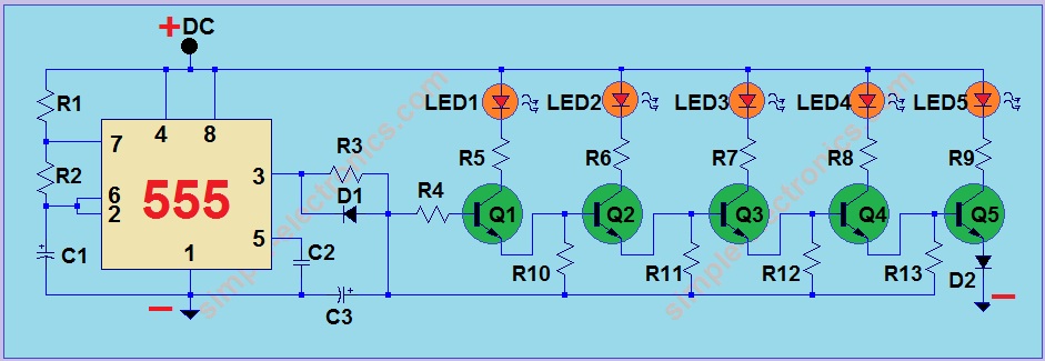
This project utilizes a 555 integrated circuit (IC) to create a sequential LED flashing effect. The configuration allows the LEDs to illuminate in a specific order, making it suitable for use as an indicator for vehicles and bicycles when...

LED lighting is becoming increasingly prominent in both residential and commercial lighting markets. To enhance the success and adoption of solid-state lighting in retrofit lamps, it is essential for LED lamps to support dimming with existing controllers and wiring....
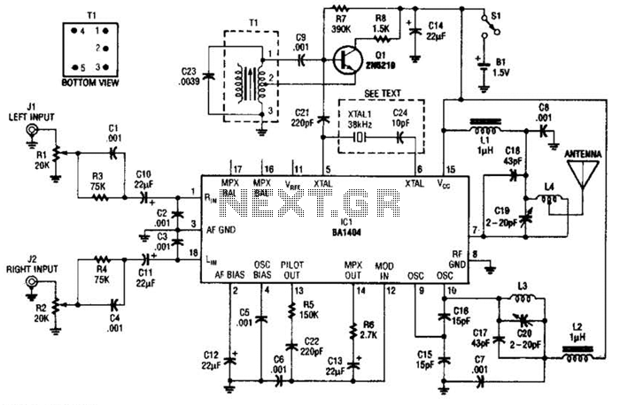
In this application, a BA1404 is utilized to generate an FM MPX baseband signal. This signal modulates a crystal oscillator (Q3) through a dual varactor series modulator. This transmitter can be used to play CD audio on an existing...
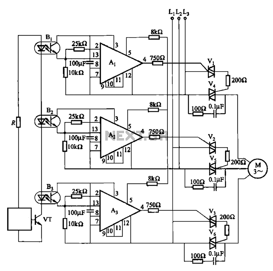
The 331 circuit depicted in the figure utilizes a two-way thyristor for controlling the start and stop functions of a motor. It operates without mechanical contacts, generating no noise or sparks, making it suitable for applications that require frequent...
Warning: include(partials/cookie-banner.php): Failed to open stream: Permission denied in /var/www/html/nextgr/view-circuit.php on line 713
Warning: include(): Failed opening 'partials/cookie-banner.php' for inclusion (include_path='.:/usr/share/php') in /var/www/html/nextgr/view-circuit.php on line 713