
PT2399 | Digital Echo Audio-Circuits

The PT2399 is a highly versatile digital echo processor that is commonly used in various audio effects applications. It operates by converting audio signals into digital format, processing them to create echo effects, and then converting the processed signals back into analog format for output. The circuit typically includes several key components, such as resistors, capacitors, and op-amps, to facilitate the necessary signal conditioning and processing.
In a typical PT2399 circuit, the input audio signal is fed into the IC, where it undergoes ADC. The internal digital processing then applies the desired echo effect, which can be adjusted by modifying feedback and delay time parameters. The output stage utilizes DAC to convert the digital signal back to an analog form, allowing it to be mixed with the original audio signal or sent directly to an amplifier or speaker.
The design of the circuit may also include additional features such as control knobs for adjusting echo depth and delay time, as well as LED indicators to provide visual feedback on the effect being applied. Proper power supply decoupling and grounding techniques are essential to minimize noise and ensure optimal performance of the circuit.
Overall, the PT2399 digital echo circuit is an effective solution for adding echo effects to audio signals, making it popular among audio engineers and hobbyists alike. Its straightforward design and ease of integration into various audio systems make it a valuable component in the realm of electronic audio processing.Circuit PT2399 digital Echo Circuit schematics Circuit Electronics, Digital Echo Processor IC PT2399 is using CMOS technology in audio purposes. digital Echo Processor PT2399 is implementing the system in the process of ADC and DAC audio r.. 🔗 External reference
Related Circuits
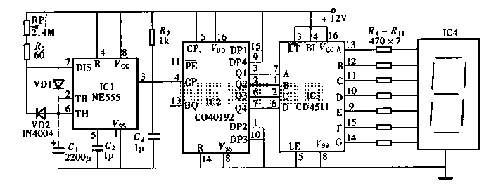
Digital timers feature a clear and precise display. They represent time intervals based on pulse signals, which are decoded by a digital device with a digital display unit. The circuit described pertains to a digital display for these timers,...
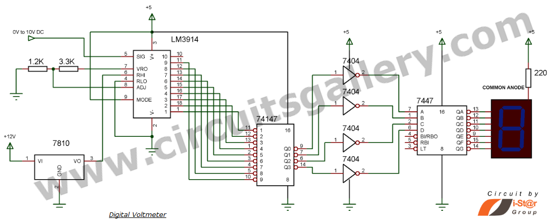
This document explains how to construct a voltmeter for measuring DC voltage without utilizing a multimeter. It describes a straightforward digital voltmeter circuit capable of measuring voltages ranging from 0V to 9V. The primary component of this circuit is...
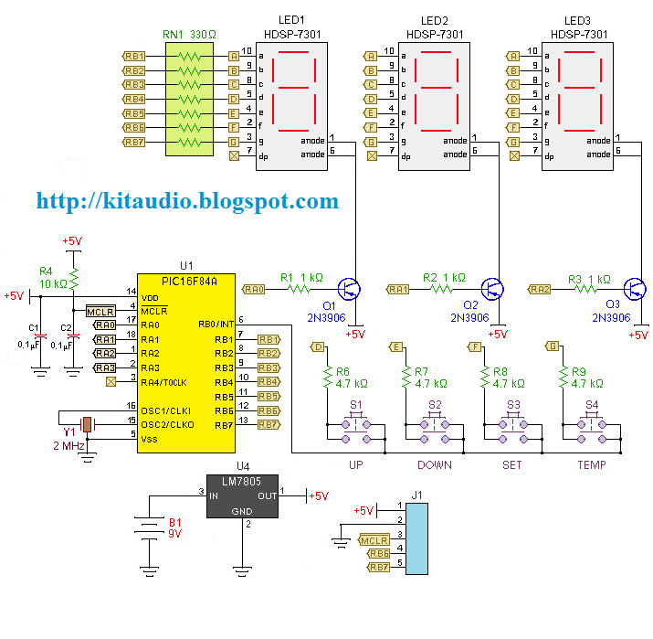
Redesign a complex solution using minimal external components, resulting in a low-cost application that provides high-precision measurements. This digital thermometer microcontroller project utilizes a watchdog timer function to measure temperature. The watchdog timer (WDT) on all PIC microcontrollers has...
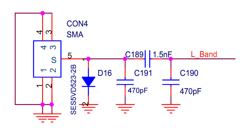
The implementation occurred in the higher frequency L-band (1452-1492 MHz), while the EU, AU, and GB operate in the VHF Band III (174-230 MHz). Unfortunately, it did not succeed for various reasons. The application works well locally, but only...
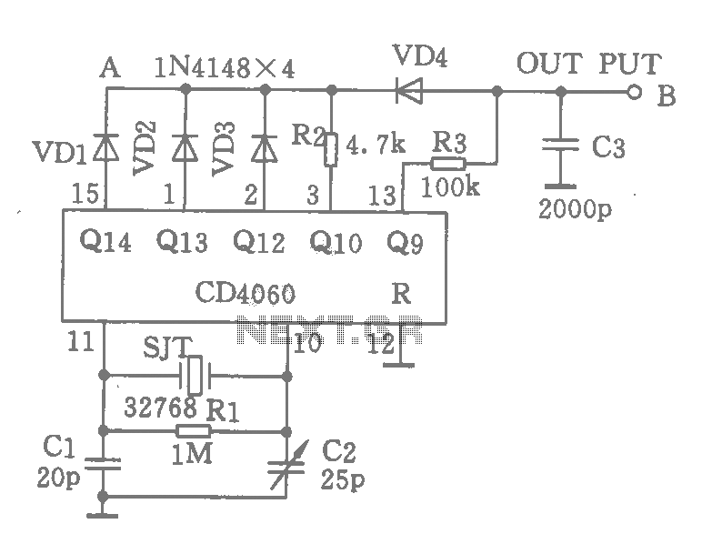
A CD4060 integrated circuit, combined with a 32,768 Hz crystal oscillator, is utilized to create a highly accurate clock source that generates 60 pulses per second. The operation is based on the division of the 32,768 Hz pulse output...
The digital readout of the Corsair 560 is positioned above the tuning knob. In this radio, the six-digit display often fluctuated, frequently doubling the frequency indication. The reading was unstable, making it challenging to determine the tuned frequency. After...