
Bridge integrated pressure signal conditioner MAX1450 drive circuit diagram
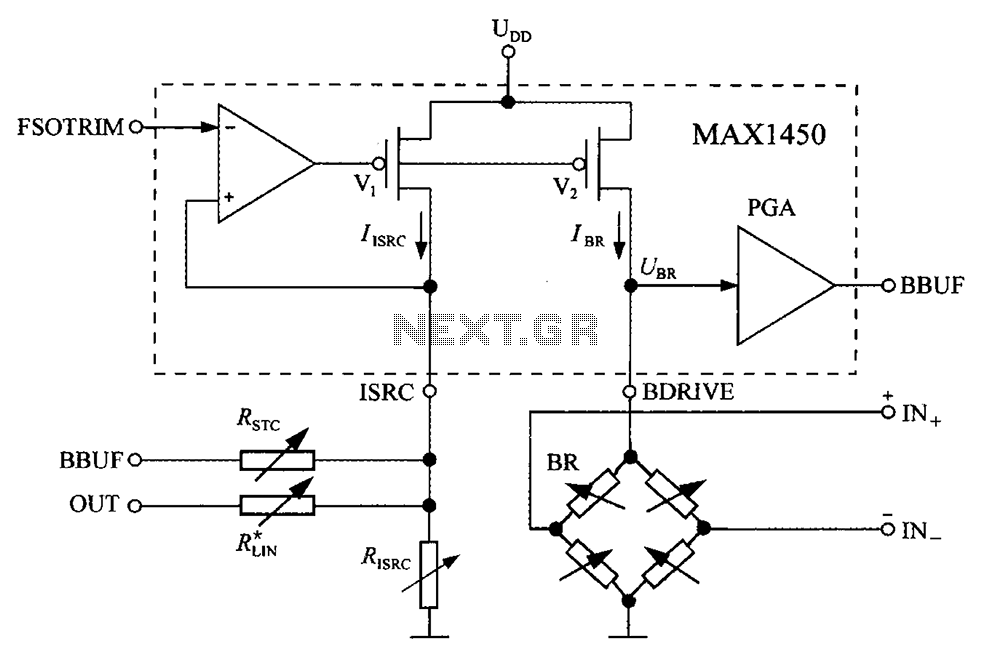
The MAX1450 is a high-performance integrated circuit designed for signal conditioning in pressure sensing applications. It is particularly suited for use with resistive bridge sensors, which are commonly employed in pressure measurement systems. The circuit typically includes an operational amplifier configuration to amplify the small differential voltage produced by the bridge sensor.
Key components of the circuit may include:
1. **Bridge Sensor**: This is the primary element that converts pressure into an electrical signal. The bridge configuration ensures that the output voltage is proportional to the applied pressure.
2. **Operational Amplifiers**: These are used to amplify the signal from the bridge sensor. The MAX1450 may contain internal op-amps or external amplifiers can be used to enhance the signal further.
3. **Reference Voltage Source**: A stable reference voltage is critical for accurate measurements. This component provides a consistent voltage level against which the bridge output can be compared.
4. **Filtering Capacitors**: To reduce noise and improve signal integrity, capacitors may be included in the circuit. These capacitors smooth out fluctuations in the output signal, resulting in a more stable reading.
5. **Gain Setting Resistors**: These resistors determine the gain of the operational amplifiers, allowing for adjustment based on the specific requirements of the application.
6. **Output Stage**: The final output stage may include a buffer or additional amplification to ensure that the signal can drive subsequent circuits or interfaces without degradation.
The layout of the circuit should be designed to minimize noise and interference, with careful consideration given to the placement of components to optimize performance. Proper grounding techniques and the use of twisted pair wiring for connections can further enhance the accuracy of the pressure measurements.
Overall, the MAX1450 drive circuit is integral to the functionality of pressure sensing systems, providing essential signal conditioning that enables precise measurement and control in various applications. Bridge integrated pressure signal conditioner MAX1450 drive circuit diagram composed of:
Related Circuits
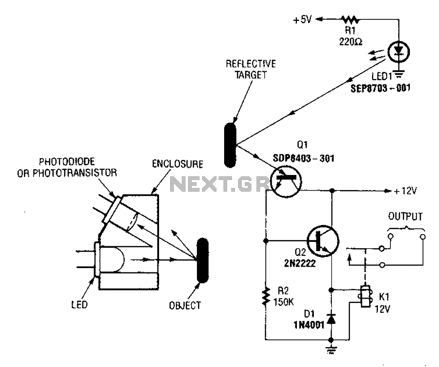
A reflex isolator detects the presence of an object by reflecting light from the object back to the sensor. This technique is effective when an object is in close proximity to the sensor. Reflex isolators, also known as proximity sensors,...
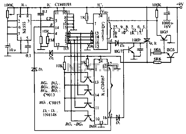
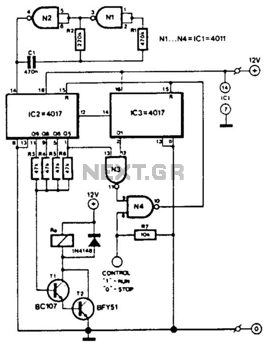
The circuit consists of an oscillator, a counter, and an Iseki circuit divided into three parts. The oscillator is based on the NE555 timer and several external RC components, generating a pulse signal for the counter. The instantaneous power...
The pulser is designed to switch the mains voltage on and off at intervals ranging from just under one second to up to 10 minutes. This functionality is particularly useful for testing mains-operated equipment over extended periods or for...
This circuit is designed for a small private telephone installation. The ringing tone sequence consists of 400 ms on, 200 ms off, 400 ms on, and 2 ms off. In the accompanying diagram, N1 and N2 create an oscillator...
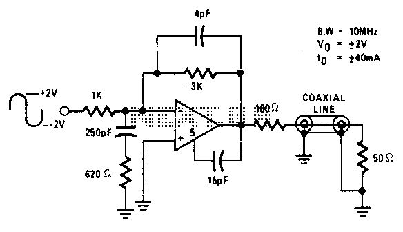
The circuit is ideal for high-frequency line driving systems that necessitate a wide power bandwidth at elevated output current levels. The integrated circuit used is HA2530. The bandwidth of the circuit is constrained solely by the single pole response...
This AC motor speed controller can handle most universal type (brushed) AC motors and other loads up to about 250W. It works in much the same way as a light dimmer circuit; by chopping part of the AC waveform...