
70W High Power Amplifier with MOSFET

The 70W power amplifier is designed to deliver high-quality audio amplification with efficient performance. The use of MOSFETs in the output stage provides several advantages, including high linearity, low distortion, and the ability to handle larger currents compared to traditional bipolar junction transistors (BJTs). This makes the amplifier capable of driving demanding speaker loads while maintaining sound fidelity.
The input stage, where audio signals are initially processed, can utilize alternative transistors such as the Toshiba 2SA970BL and 2SC2240BL. These transistors are chosen for their excellent frequency response and low noise characteristics, which are critical for maintaining audio clarity. The circuit configuration may include biasing resistors and capacitors to ensure stable operation and proper signal coupling.
In the output stage, the MOSFETs are typically arranged in a complementary push-pull configuration to improve efficiency and reduce crossover distortion. The power supply section should be designed to deliver adequate voltage and current, with decoupling capacitors included to filter out noise and stabilize the power rails.
Overall, the schematic represents a robust design suitable for high-performance audio applications, with flexibility in component selection to accommodate different performance needs and availability of parts. Proper thermal management should also be considered, as MOSFETs can generate significant heat during operation, necessitating adequate heat sinking and ventilation in the final assembly.Here the schematic diagram of 70W power amplifier with MOSFET for your audio system. There are possible alternative input stage transistors, the Toshiba 2SA970BL and 2SC2240BL, which appear to be good substitutes for the Hitachi 2SA1085E an.. 🔗 External reference
Related Circuits
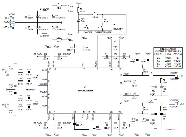
This high-power Class D audio amplifier electronic project is designed using the TDA8920BTH audio power amplifier IC. This power amplifier IC offers very high efficiency with minimal dissipation, yielding significant output power. The typical output power is 200 watts...
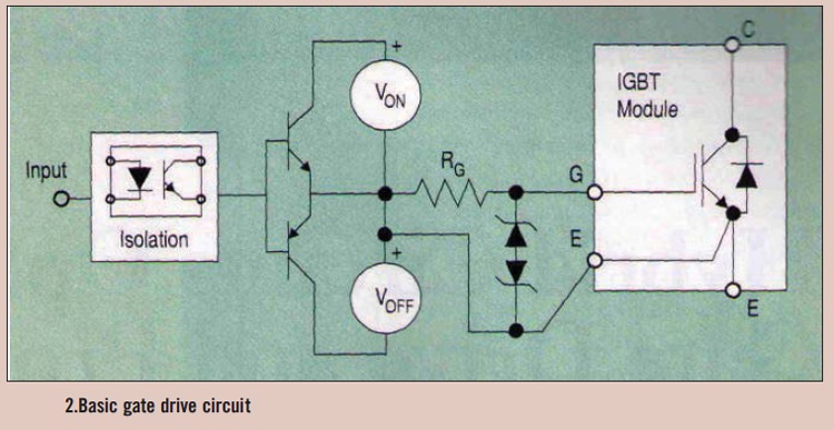
High power IGBT modules utilize hybrid integrated circuit (IC) gate drives that incorporate protection circuits, which implement desaturation detection or real-time control. High power Insulated Gate Bipolar Transistor (IGBT) modules are essential components in various high-efficiency power conversion applications, such...
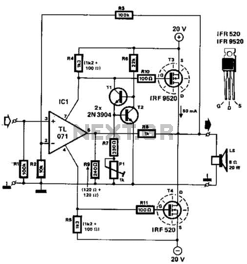
Two complementary MOSFETs are utilized to deliver 20 W into an 8-ohm load. A TL071 operational amplifier serves as the input amplifier. The MOSFETs must be equipped with a heatsink that has a thermal resistance of better than 5...
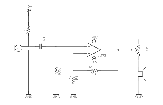
Afroman discusses the fundamentals of utilizing an operational amplifier to amplify small voltage signals and constructs a circuit designed to detect very faint sounds using a microphone. For further details about amplifiers, it is recommended to search for inverting...
Power an RS232-TTL converter circuit using the serial port to eliminate the need for an external power supply. It has been noted that the DTR, RTS, and TD pins can facilitate this. Since the TD pin is already utilized...
This design addresses the limitations of the microphone preamp in the Sony R91, which clips at low levels, providing only 28mV of headroom for an input that may reach 1800mV, depending on the microphone and volume settings. The design...