
72 LED Clock
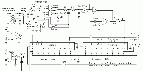
The clock circuit utilizes a total of 72 LEDs, with 60 dedicated to minute indication and 12 for hour representation. The 74HCT164 is an 8-bit serial-in, parallel-out shift register, which is essential for managing the LED outputs. In this design, eight of these shift registers are connected in a cascade configuration, enabling a single bit to circulate through all 60 LEDs. This configuration allows for the representation of each minute in a standard hour.
The power supply circuitry is designed to provide a stable voltage suitable for the operation of the LEDs and the shift registers. Typically, a regulated DC voltage source, such as +5V, is utilized to ensure consistent performance. The time base circuitry, likely based on a crystal oscillator or a timer IC, generates the necessary clock pulses to drive the shift registers. This clock signal is crucial for shifting the bits through the registers at the correct intervals, thus illuminating the appropriate LED for the current minute.
In terms of LED operation, each minute corresponds to a unique LED being lit, while the hour indication is handled separately with 12 LEDs, which may be controlled by another set of shift registers or a different logic mechanism. The cascading of the shift registers allows for seamless transition from one minute to the next, with the LEDs illuminating in a sequential manner, providing a clear visual representation of the time.
Overall, this clock design effectively combines digital logic with visual output, utilizing standard components to achieve a functional and visually appealing timekeeping device.In the circuit, 60 individual LEDs are used to indicate the minutes of a clock and 12 LEDs indicate hours. The power supply and time base circuitry is the same as described in the 28 LED clock circuit above. The minutes section of the clock is comprised of eight 74HCT164 shift registers cascaded so that a single bit can be recirculated through the 60 stages indicating the appropriate minute of the hour
🔗 External reference
Related Circuits

The E1T counting tube is one of the most fascinating tubes ever created. Developed by Philips between 1946 and 1954, it has a unique origin story detailed in other studies. A primary challenge in using this tube for clock...
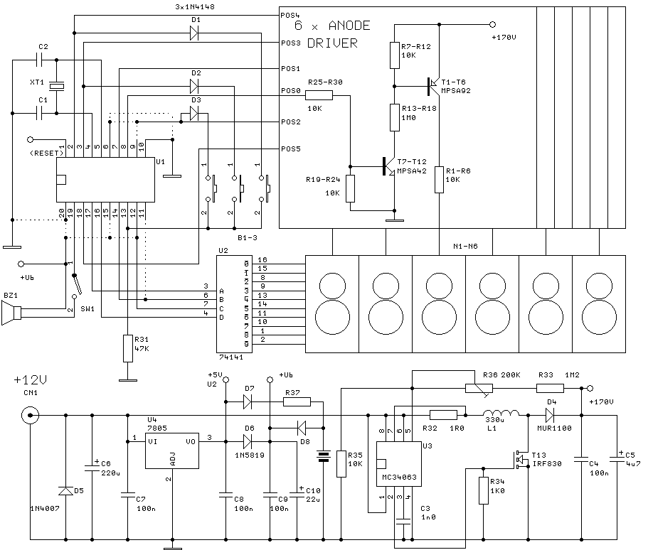
The clock will have 6 digits and time setting will be done by means of a few buttons. I will try to use the most common types from widely used microcontroller families of miscellaneous producers. I will write the...
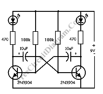
This LED flasher circuit is a classic two-transistor flip-flop. It is a popular circuit often built by beginners in the electronics hobby. The schematic diagram of this well-known LED flasher circuit includes two transistors, two capacitors, four resistors, and...
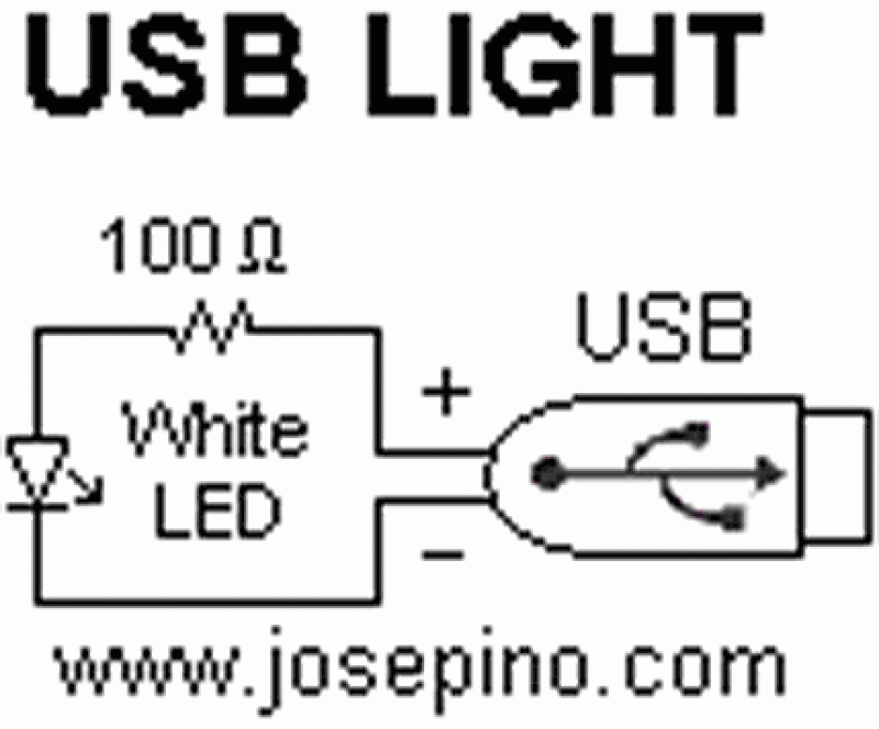
This is a simple LED circuit that takes power from the USB port. I needed this USB light since long time ago but, finally, I was able to build it. The circuit schematic is so simple: Just one resistor...
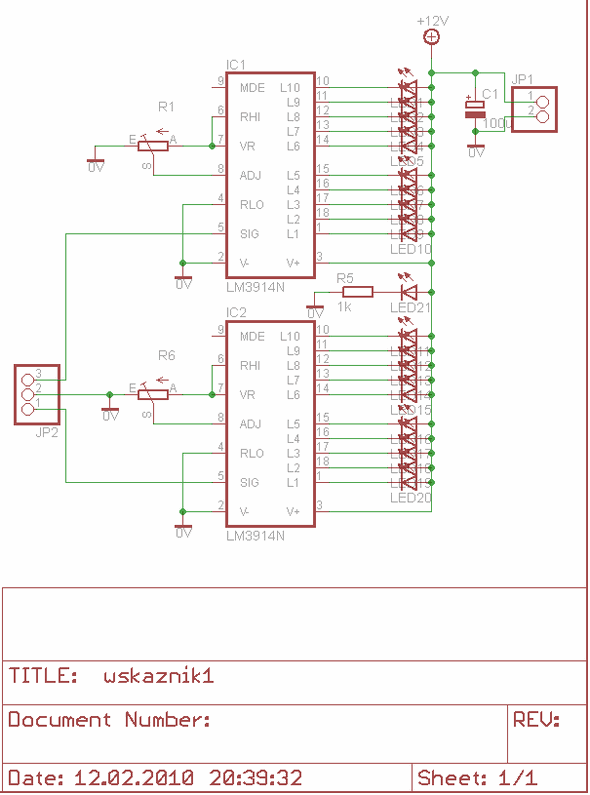
The LM3914 is a monolithic integrated circuit designed to sense analog voltage levels and drive a 20 LED stereo VU meter. It features a circuit diagram for a PCB layout using Eagle software, specifically for a 10 LED stereo...
A beep or metronome-like click and/or a visible flash will indicate a one-second interval, which can be useful in various applications requiring time-delay counting in seconds. The circuit utilizes a CMOS 4024 counter/divider chip and three diodes, configured to...
Warning: include(partials/cookie-banner.php): Failed to open stream: Permission denied in /var/www/html/nextgr/view-circuit.php on line 713
Warning: include(): Failed opening 'partials/cookie-banner.php' for inclusion (include_path='.:/usr/share/php') in /var/www/html/nextgr/view-circuit.php on line 713