
74S124 High Frequency VCO with Varactor
The schematic for the voltage-controlled oscillator (VCO) circuit incorporates several key components that facilitate its operation. The 74S124 multivibrator, known for its high-speed performance, serves as the core of the circuit. The integration of the Philips BB909A varactor allows for the modulation of capacitance in response to an input voltage, which directly influences the frequency output of the oscillator.
The coupling capacitors, C1 and C2, play a critical role in ensuring that the varactor operates effectively within the desired frequency range. The selection of capacitor values is crucial; for instance, using 47 pF capacitors allows operation within the 6.8 to 72 MHz range, while 22 nF capacitors extend the range to 2.2 to 65 MHz. This flexibility makes the circuit adaptable to various applications, including radio frequency tuning and signal processing.
Resistors R1 and R2 are strategically placed to isolate ground and control voltages from the timing capacitors, preventing unwanted interference in the oscillator's operation. The inclusion of a potentiometer as a voltage divider provides a means to finely adjust the capacitance of the varactor, thereby allowing for precise control over the output frequency. In scenarios where external voltage signals are utilized, the potentiometer can be bypassed, simplifying the circuit design and enhancing integration with other systems.
The VCO's ability to interface with digital systems through a DAC makes it especially valuable in hybrid applications. This capability enables the generation of variable frequencies that can be used in programmable filters and other analog processing tasks, providing a bridge between digital control and analog signal processing.
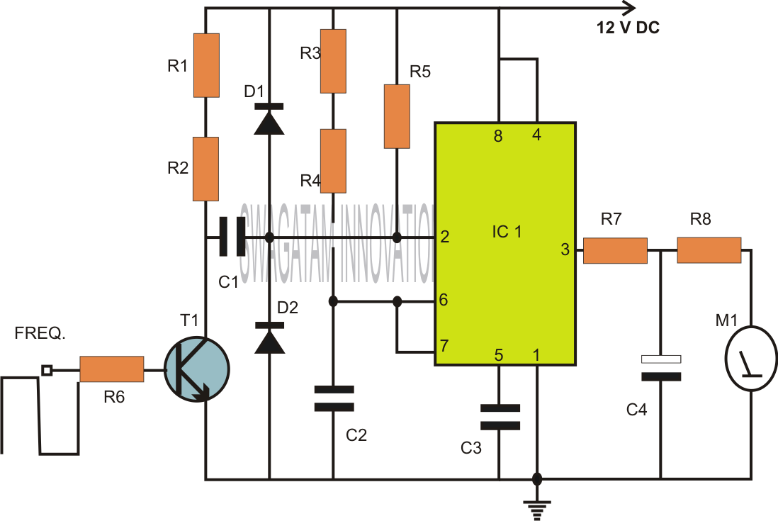
In summary, the voltage-controlled oscillator circuit described is a versatile and high-performance solution for generating variable frequency signals, suitable for a wide range of electronic applications. The careful selection of components and design considerations ensures that the circuit operates effectively across various frequency ranges while maintaining compatibility with digital control systems.The following schematic diagram shown a conventional which is modified to become a VCO (voltage-controlled oscillator) circuit. By replacing the conventional fixed capacitor with a variable capacitance diode (varactor), we can turn a 74S124 multivibrator into a wide-band VCO.
High speed logic 74S series is used here to enable this circuit for high frequency operation. Here is the schematic diagram of the circuit: The need of a relatively high voltage source, the 30 V biasing voltage that the diode requires is the only disadvantage of this scheme. We can use lower voltage for this, but it means the VCO would be no more wide-range. Capacitors C1 and C2 couple the Philips BB909A variable capacitance diode to the 74S124. This capacitors can be selected to different values to accommodate different frequency range. Use C1 = C2 = 47pF for 6. 8 to 72 MHz, and use C1 = C2 = 22nF for 2. 2 to 65 MHz. R1 and R2 are large enough to isolate ground and control voltages from the timing capacitors. The potentiometer is used as a voltage divider for controlling the capacitance of varactor, thus controlling the frequency of this VCO circuit.
This potentiometer can be omitted if we control this circuit using voltage signal from other devices, replacing the center tap of this potentiometer. In hybrid system, analog system with digital control, a voltage controlled things is very important since it can be interfaced by DAC from digital system.
For radio tuning with digital control, a voltage controlled LC circuit is needed. If we Continue reading †’. VCO (voltage controlled oscillator) is an electronic signal generator which produce a signal that has variable frequency depends on a voltage level at its control input. Many VCO circuits are based on ramp generator to produce a variable frequency output, Continue reading †’.
An oscillator can be built using LC (inductor-capacitor) tank circuit. When we vary the capacity of the capacitor in LC tank circuit then the frequency of the oscillator will vary according to capacitance change. The idea of this modulator is Continue reading †’. Capacitance multiplier simulate high capacitance capacitor for analog signal signal processing. By using DAC (Digital-to-Analog Converter), we can simulate variable capacitance with very wide range, which can be used in digitally controlled analog processor (programmable filters for example).
The following Continue reading †’. Function generator ranging from 0. 1 Hz to 20 MHz can be easily built using MAX038 integrated circuit chip. Here is the most simple implementation of high frequency sine wave generator, and you can easily modify it to generate square wave, Continue reading †’. 🔗 External reference
Related Circuits
Homemade antennas can significantly enhance the performance of AM and FM radios, short-wave receivers, and scanners. For enthusiasts of talk radio, experimenting with AM band antennas can lead to the ability to receive broadcasts from across the country with...
Capacitors are major electronic components classified as passive components. They are extensively used in electronic circuits, and virtually no circuit can be constructed without these essential parts. The primary function of a capacitor is to block direct current (DC)...
As power supply switching frequencies increase, higher loop crossover frequencies are necessary to keep pace with the escalating load transient slew rate demands and to reduce the number and size of filter components. For voltage-mode-controlled supplies, the voltage loop...
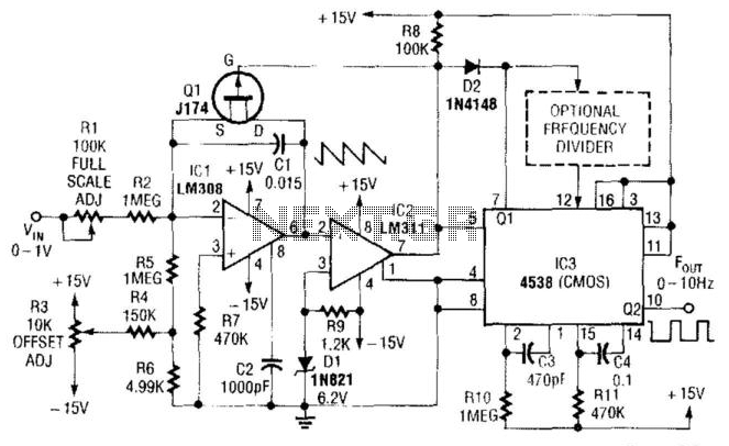
In this circuit, capacitor CI is charged to a fixed reference level and then discharged. The integrator IC1 charges CI until IC1 has a -6.2 V output, at which point comparator IC2 outputs a low signal. FET Q1 triggers...
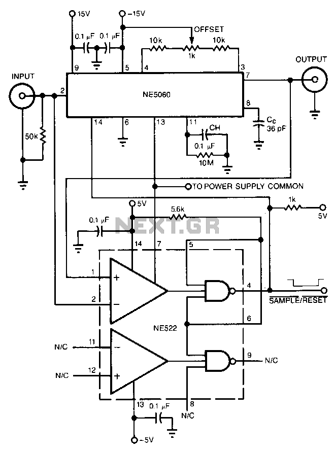
The high-speed peak detector utilizes a highly accurate, fast sample-and-hold (s/h) amplifier that is controlled by a high-speed comparator. The s/h amplifier retains the peak voltage until the comparator switches the amplifier to its sample mode to capture a...

This application note discusses the use of SEPIC power modules to supply the necessary power for driving high-brightness LED arrays. These arrays serve as display backlights and necessitate a wide dimming range. The SEPIC configuration offers an efficient and...