
how to build inexpensive frequency
The circuit design for the capacitance and frequency meter begins with the configuration of the IC 555 in its monostable mode. This mode is selected for its ability to produce a single output pulse in response to an input trigger, making it ideal for measuring time intervals and frequencies. The timing interval is determined by the resistor and capacitor connected to the IC, specifically through the use of a variable resistor (preset P1) that allows for fine-tuning of the output period. The pulse width generated can be adjusted to accommodate different frequency ranges, making the meter versatile for various applications.
The input signal is fed into pin #2 of the IC 555, where it is detected and processed. When a positive pulse is received, the IC generates an output pulse that is proportional to the duration of the input signal. This output pulse can be observed on an oscilloscope or through an LED indicator, providing visual feedback on the frequency being measured.
To measure capacitance, an external frequency generator can be introduced into the circuit. The frequency generator produces a known frequency signal that is applied to the capacitor under test. As the capacitance of the capacitor changes, it alters the frequency of the output signal from the IC 555. By analyzing the relationship between the frequency output and the capacitance value, users can determine the capacitance of the unknown capacitor.
The implementation of this circuit requires a few additional components, including resistors, capacitors, and a power supply. The choice of resistors and capacitors will affect the overall performance and range of the meter. It is essential to select components that are rated for the expected voltage and frequency ranges to ensure accurate measurements and reliable operation.
In summary, this capacitance and frequency meter circuit, built around the IC 555, provides an accessible solution for hobbyists and engineers alike. It combines functionality and simplicity, enabling users to measure capacitance and frequency with minimal investment in components and equipment. This makes it an invaluable tool for educational purposes, prototyping, and general electronics experimentation.Capacitors are one of the major electronic components which come under the passive component family. These are extensively used in lectronic circuits and virtually no circuit can be built without involving these important parts. The basic function of a capacitor is to block DC and pass AC or in simple words any voltage which is pulsating in na
ture will be allowed to pass through a capacitor and any voltage that`s not polarized or direct will be blocked by a capacitor by the process of charging. However unlike resistors, capacitors are difficult to measure through ordinary methods. For example, an ordinary multitester might have many measuring features included like an OHM meter, voltmeter, ammeter, diode tester, hFE tester etc.
but might just not have the illusive capacitance measuring feature. The feature of a capacitance meter or an inductance meter is seen to be available only in high end type of multimeters which are definitely not cheap and not every new hobbyist might be interested in procuring one. The circuit discussed here very effectively tackles these issues and shows how to build a simple inexpensive capacitance cum frequency meter which can be built at home by any electronic novice and used for the intended useful application.
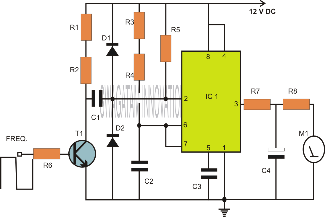
Referring to the figure, the IC 555 forms the heart of the entire configuration. This work horse versatile chip is configured in its most standard mode that is the monostable multivibrator mode. Every positive peak of the pulse applied at the input that is pin #2 of the IC creates a stable output with some predetermined fixed period set by the preset P1.
This generates a kind of an average value at the output of the IC for which is directly proportional to the frequency of the applied clock. In other words the output of the IC 555 which consists of a few resistors and capacitors integrates the series of pulses to provide a stable average value directly proportional to the applied frequency.
Now looking at the next figure we can clearly see that by adding an external frequency generator to the previous circuit, it becomes possible to make the meter interpret the values of a capacitor across the indicated points, because this capacitor directly affects or is proportional to the frequency of the clock circuit. That means now we have a two in one circuit which can measure capacitance as well as frequency, using just a couple of ICs and some casual electronic parts.
🔗 External reference
Related Circuits
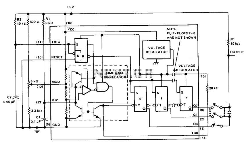
The µA2240 consists of four basic circuit elements: (1) a time-base oscillator, (2) an eight-bit counter, (3) a control flip-flop, and (4) a voltage regulator. The basic frequency of the time-base oscillator (TBO) is set by the external time...
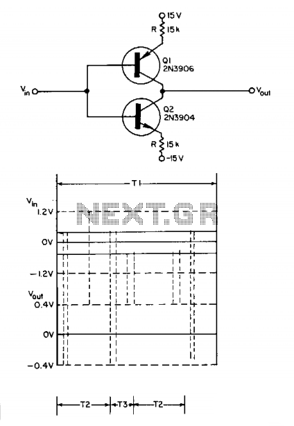
The turn-on and turn-off characteristics of two complementary transistors can be combined to achieve nonselective frequency tripling. The resulting circuit processes any periodic waveform with non-vertical edges. Each peak of the input signal generates three output signal peaks. The...
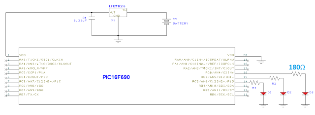
Below is the schematic integrated with the voltage regulator from the previous post. The PIC16F690 serves as the central controller of the system. This microcontroller is a mid-range option for hobbyists, offering more functionality than utilized in this project....
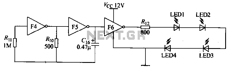
Gates F4, F5, and F6 together form a low-frequency oscillator that drives high-brightness light-emitting diode (LED) flashes. The light-emitting diodes may be arranged around the booth seat for decorative purposes. The automatic referral machine is used prior to operation...
This is a handy companion for a digital voltmeter. Its allowed me to do a lot of things I used to use my oscilloscope for, and in addition it measures voltages to much greater precision. Using an LM324 quad...
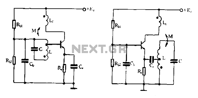
Base frequency selection, frequency-selective emitter type transformer coupled oscillator circuit The described circuit is a transformer-coupled oscillator that utilizes an emitter type configuration to achieve frequency selection. This type of oscillator is designed to generate signals at specific base frequencies,...