
AM Receiver Circuit Using Transistor

The circuit design integrates several critical components that enhance its functionality. The BC549 transistors are chosen for their favorable characteristics, including low noise and high gain, which are essential for radio frequency applications. The regenerative feedback mechanism provided by the 120k ohm resistor is a key feature that allows for amplification of weak signals, thereby improving the overall sensitivity of the receiver.
The tuning circuit, which consists of the tuning coil and a variable capacitor, allows for the selection of the desired frequency. The use of a ferrite rod as a core for the tuning coil is advantageous as it increases the inductance, which in turn enhances the quality factor (Q) of the circuit, leading to better selectivity.
In practical applications, adjustments can be made to the tuning coil and capacitor to optimize the circuit for specific frequency ranges. For higher frequency operation, the inductance of the coil can be decreased by reducing the number of turns or by using a different core material.
Additionally, the circuit's layout should be considered to minimize parasitic capacitance and inductance, which can adversely affect performance. Proper grounding techniques and component placement can significantly influence the stability and reliability of the receiver.
Overall, this simple three-transistor regenerative receiver circuit is an excellent choice for medium wave and higher frequency applications, providing a robust platform for further experimentation and refinement in radio frequency engineering.This is the simple design and sensitivity and selectivity of the receiver are good. This circuit is use a compact three transistor, regenerative receiver with fixed feedback. The circuit is based on transistor as core of the operation. The transistor that is used is BC549. This is the figure of the circuit. The tuned circuit is designed for medium wave, but the circuit will work up to much higher frequencies if a different tuning coil and capacitor are used. Q1 and Q2 form a compound transistor pair featuring high gain and very high input impedance. This is necessary so as not to unduly load the tank circuit. Q1 operates in emitter follower, Q2 common emitter, self stabilizing bias is via the 120k resistor and the tuning coil.
As Q2 operates in common emitter its base voltage will be a V be drop higher than ground or about 0. 71V in my test sample. The 120k resistor provides regenerative feedback, between Q2 output and the tank circuit input and its value affects the overall performance of the whole circuit. The tuning coil can be salvaged from an old AM receiver. However to make your own wind about 50 to 60 turns of 26 swg enamel coated copper wire over a 3/8 inch ferrite rod about 3 inches long.
This circuit is powered by 9 VDC. 🔗 External reference
Related Circuits
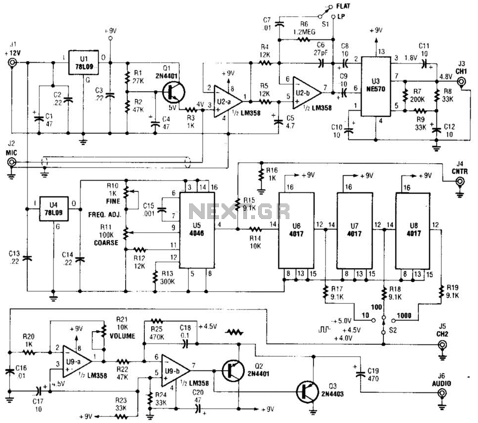
The precision audio frequency generator consists of several sub-circuits: an audio amplifier/filter circuit, an automatic level control, a variable voltage-controlled oscillator, a frequency divider circuit, an integrator, and an audio output amplifier. An electret microphone element is utilized to...
To achieve optimal performance from an NBTV signal, it is crucial to utilize the complete dynamic range of the signal without any crushing at the black level or peak white. To evaluate the linearity of a video path, it...
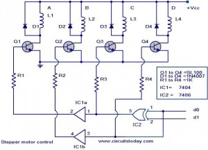
The following circuit illustrates a Stepper Motor Controller Circuit Diagram. This circuit is based on the 7404 IC. Features include a simple stepper motor. The stepper motor controller circuit utilizing the 7404 IC is designed to drive a stepper motor...
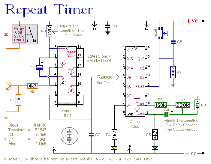
This circuit features an adjustable output timer capable of re-triggering at regular intervals. The output duration can range from a fraction of a second to over half an hour, and it can be configured to recur at regular intervals...
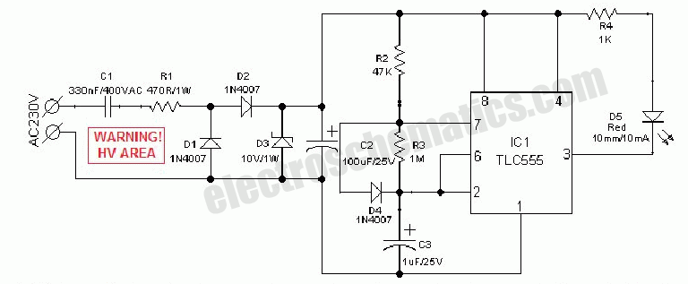
An AC mains operated single LED flasher circuit is constructed using the widely utilized CMOS timer chip TLC555. The entire circuit is powered directly from the 230VAC grid supply via a capacitive potential divider and associated components. This compact...
This device is designed to be a simple, inexpensive comparator intended for use in a solar cell power supply setup where a quick indication of "too low" or "just right" voltage is needed. The circuit consists of one 5V...