
MHz FREQUENCY COUNTER
The 2-MHz frequency counter circuit is designed to accurately measure and display frequency signals, utilizing a combination of integrated circuits and discrete components to achieve its functionality. The LSI counter/display driver is central to the operation, allowing for seamless interaction with the LCD readout. The LCD-004 display is specifically chosen for its compatibility with the ICM7224IPL, which integrates both counting and display driving capabilities, thereby minimizing the component count and simplifying the design.
The signal input amplification is critical for enhancing the weak frequency signals received. Transistors Q2 and Q3 are configured to amplify the input signal before it is processed by the counter. This amplification stage ensures that the frequency counter can accurately detect and measure lower amplitude signals, which is essential for reliable performance in various applications.
The crystal oscillator circuit, featuring U3-c and XTAL1, is responsible for generating a stable timing reference essential for frequency measurement. The oscillator operates at a fundamental frequency, which is then divided down to create additional timing references. This division is accomplished through digital logic circuits, allowing for the selection of different timing reference signals based on the application's requirements. The availability of three selectable timing references enhances the versatility of the frequency counter, making it suitable for a wider range of measurement tasks.
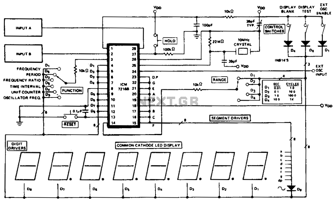
In summary, the design of this 2-MHz frequency counter incorporates a well-defined architecture that integrates an LSI counter/display driver, an LCD readout, and necessary logic circuitry to provide accurate frequency measurements. The use of a crystal oscillator for timing reference, along with a multi-stage signal amplification approach, underscores the careful consideration of performance and reliability in the design of this electronic measurement instrument.This is a schematic and block diagram of a 2-MHz frequency counter. It uses and LSI counter/display driver, LCD readout, and a, few logic chips for timebase and timing pulse circuitry. Q2 and Q3 form a signal (input) amplifier. The circuit contains a crystal oscillator built around U3-c and XTALl, which provides the pri-mary timing-reference signal
. That signal is then divided twice to provide two additional timing ref-erences, giving the circuitry three selectable timing references. The ICM7224IPL is an integrated circuit that consists of the counter and display driver to drive the LCD-004 display.
🔗 External reference
Related Circuits
By using transformers, both voltage feedback and current feedback can be applied. An article by DJ2LR Ulrich Rohde in Ham Radio, November 1979, provides details about this circuit. For the 2.5 MHz to audio converter, the transformation ratio from...
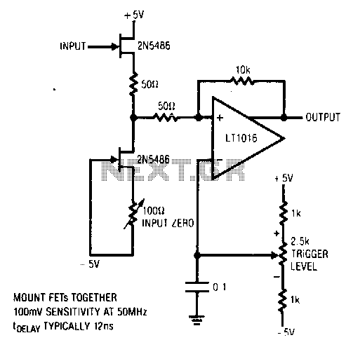
This circuit features a stable trigger with a sensitivity of 100 mV at 50 MHz. It utilizes FETs to create a high-speed buffer, while the LT1016 compares the output of this buffer to the voltage at the trigger level...
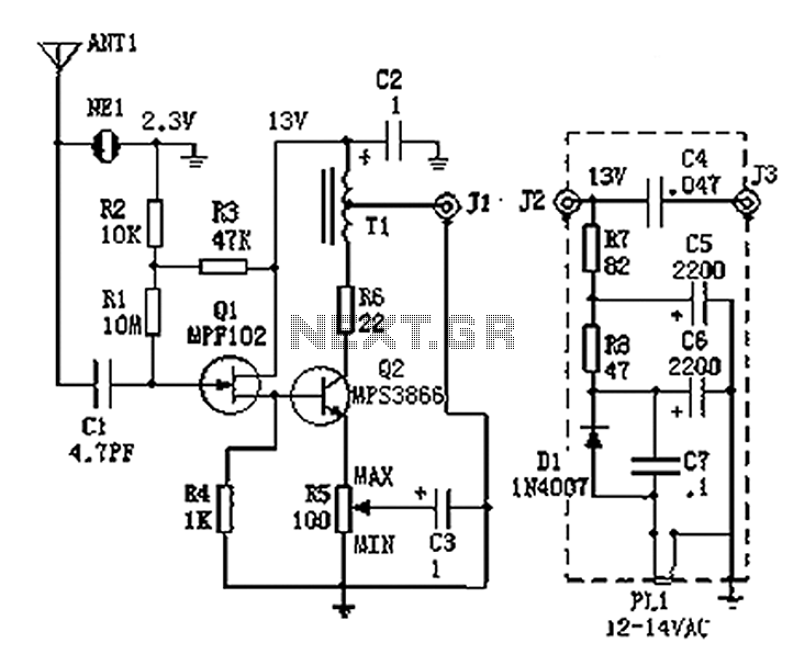
An active antenna operating within the frequency range of 100 kHz to 30 MHz, characterized by its compact size and effective performance. It is designed to be simple and low-cost, making it ideal for remote medium wave and short-wave...
A wideband transmission or communication channel consists of a broader bandwidth than a single voice channel, utilizing a carrier wave of a specific modulated frequency. This allows for the transmission of more information than narrowband systems, but less than...
The ICM7216A can be utilized as a complete universal counter with minimal components. This circuit is capable of handling input frequencies of up to 10 MHz at INPUT A and 2 MHz at INPUT B. In cases where the...
A function generator that operates within a frequency range of 0.1 Hz to 20 MHz can be constructed using the MAX038 integrated circuit chip. This represents a straightforward implementation of a high-performance signal generator. The MAX038 is a high-speed precision...