
8 MHz frequency meter using AVR microcontroller
The circuit for this project primarily consists of an AVR microcontroller, a clock source, and a display unit. The microcontroller is programmed to count the number of clock pulses received at its Timer input over a specified interval, in this case, one second.
The clock source can be any signal generator or oscillator that outputs a square wave signal, which serves as the input to the Timer. The Timer input pin of the microcontroller is configured to detect the rising or falling edges of the clock pulses, depending on the specific requirements of the application.
The Bascom code is responsible for initializing the Timer and configuring the necessary registers to enable counting. It sets up an interrupt or polling mechanism to capture the clock pulses accurately. After the counting period of one second, the code retrieves the count value from the Timer register and sends it to a display unit, which can be an LCD or LED display.
The display unit is connected to the microcontroller through appropriate data and control lines, allowing it to present the counted value in a readable format. The entire system is powered by a suitable power supply, ensuring that all components operate within their specified voltage and current ratings.
In summary, this project combines microcontroller programming, hardware interfacing, and display technology to create a functional clock pulse measurement system.This project can measure the clock pulses fed to the Timer input of the AVR microcontroller. The Bascom code counts the clock pulses for 1 second and display it. 🔗 External reference
Related Circuits
The LM3915 is a monolithic integrated circuit that senses analog voltage levels and drives ten LEDs providing a logarithmic 3 dB/step analog display. LED current drive is regulated and programmable, eliminating the need for current limiting resistors. The IC...
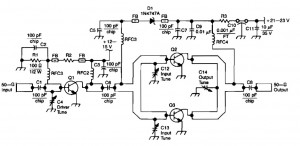
This RF amplifier circuit delivers a power output of 4 Watts at a frequency of 900 MHz. It utilizes Wilkinson power dividers in the base and collector circuits of transistors Q2 and Q3. Two SD1853 driver application transistors are...
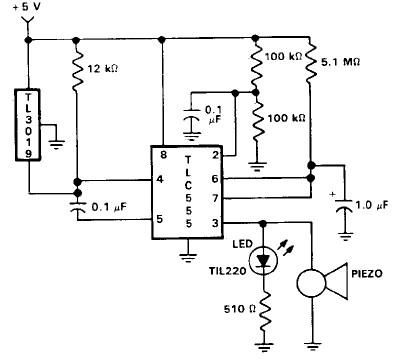
This door open alarm electronic project is designed using a linear hall effect device and a 555 timer circuit. The project utilizes the TL3103 linear hall effect device for detecting the angle of rotation. The TL3103 is positioned within...
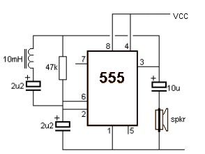
A simple metal detector circuit can be implemented using a 555 timer chip. The schematic diagram illustrates that this project requires only a few external electronic components. The metal detector circuit utilizing a 555 timer operates in astable mode, generating...
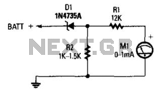
A Zener diode (D1) is utilized to limit the voltage to the first 6 V of the scale, resulting in a meter reading range of 6 to 8 V, which is beneficial for monitoring automotive electrical systems. The circuit employs...
The circuit was designed to create ten different frequency bands that can be processed by a single graphic equalizer to produce and maintain a predetermined frequency response. The described circuit is a graphic equalizer that utilizes a multi-band approach to...
Warning: include(partials/cookie-banner.php): Failed to open stream: Permission denied in /var/www/html/nextgr/view-circuit.php on line 713
Warning: include(): Failed opening 'partials/cookie-banner.php' for inclusion (include_path='.:/usr/share/php') in /var/www/html/nextgr/view-circuit.php on line 713