
Door open alarm using 555 timer circuit
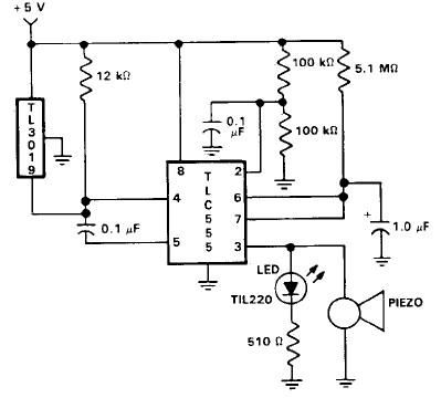
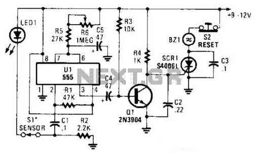
The door open alarm circuit integrates a TL3103 linear hall effect sensor, which is sensitive to magnetic fields and is essential for detecting the position of the door. When the door is closed, the U-shaped permanent magnet keeps the TL3103 sensor in a state that outputs a low signal. This low signal keeps the 555 timer in a stable state, preventing any alarms from triggering.
Upon opening the door, the magnetic field around the TL3103 is disrupted, causing the output to switch to a high state. This change is detected by the 555 timer circuit, specifically at the trigger pin (pin 2). The low state at pin 2 must be momentarily interrupted to initiate the timing cycle of the 555 timer. This is achieved by applying a positive pulse, which can be coupled through a capacitor (0.1 µF) to control pin 5, allowing the timer to reset via pin 4.
The 555 timer, configured in monostable mode, starts a timing interval once triggered. The duration of the output high state at pin 3 can be adjusted by changing the resistance and capacitance values connected to the timer. During the timing cycle, both the piezoelectric alarm and an LED indicator are activated, providing both auditory and visual alerts that the door has been opened.
To enhance the functionality of the alarm system, additional elements such as a power supply circuit can be integrated to ensure the device operates reliably. Moreover, incorporating a debounce circuit could prevent false triggering due to mechanical vibrations when the door is opened or closed. Such improvements can lead to a more robust and user-friendly door open alarm system.This door open alarm electronic project is designed using an linear hall effect device and a 555 timer circuit. This door open alarm alarm electronic project is based on the TL3103 linear hall effect device used for detecting the angle of rotation.
The TL3103s are centered in the gap of a U-shaped permanent magnet. Usually a 555 timer circuit is t riggered by taking the trigger, pin 2, low which produces a high at the output, pin 3. In this configuration with the door in the closed position, the TL3019 output is held low. The trigger, pin 2, is connected to Vi the supply voltage Vcc. When the door opens, a positive high pulse is applied to control pin 5 through a 0. 1 uF capacitor and also to reset pin 4. This starts the timing cycle. Both the piezo alarm and the LED visual indicator are activated. 🔗 External reference
Related Circuits
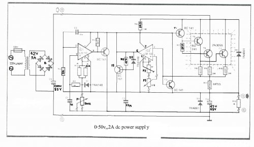
The LM10 integrated circuit (IC) is utilized due to its reference voltage feature, which is advantageous for DC power supply applications. By employing two LM10 ICs, different output voltages and current levels can be achieved. This circuit includes short-circuit...

A cell phone jammer is an electronic device designed to obstruct the transmission of signals between a cell phone and its nearby base station. By transmitting on the same frequency as cell phones, the jammer generates significant interference, disrupting...
How the processor produces 3 as the output. This question may be challenging to answer in simple terms. If so, a link to a book would be helpful. The process by which a processor generates the output of the number...
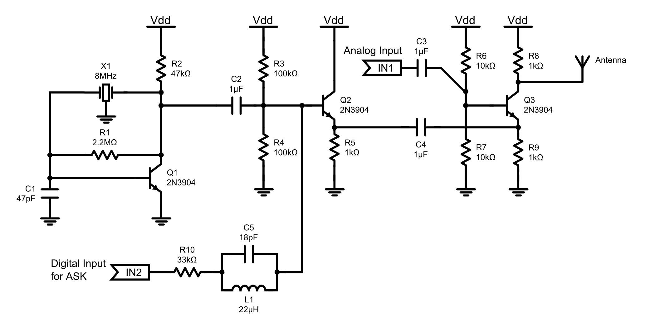
This is an 8MHz amplitude modulated (AM) radio transmitter designed primarily for practical applications and as an educational exercise in electronics. The objective was to create a simple radio transceiver that could be used in future projects requiring basic...
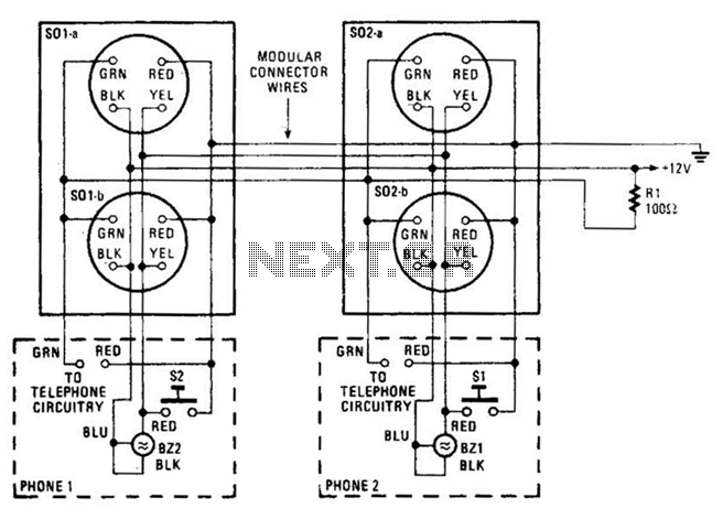
An intercom utilizing dual-modular wall jacks is depicted in this circuit. If the wires are accessible in the home telephone cable, this system can be installed with minimal difficulty. The intercom system described employs dual-modular wall jacks, which are standard...
The alarm circuit utilizes a single 555 oscillator/timer (U1) that functions in both the alarm-trigger circuit and the entry-delay circuit. In this configuration, the trigger input of U1 at pin 2 is maintained in a high state through resistor...