
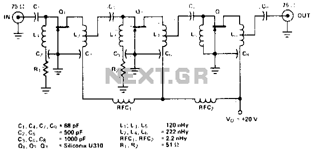
4 watt 900mhz rf amplifier

The RF amplifier circuit is designed to operate efficiently at a frequency of 900 MHz, making it suitable for various wireless communication applications. The use of Wilkinson power dividers in the circuit is critical for achieving balanced power distribution and minimizing signal reflections. These dividers ensure that the input power is evenly split between the two driver transistors, Q2 and Q3, which are both SD1853 types.
The SD1853 is specifically chosen for its high gain and efficiency, enabling the amplifier to produce a total output of 4 Watts. By paralleling two of these transistors, the circuit effectively doubles the power output compared to a single transistor configuration, which typically provides around 2 Watts. This parallel arrangement also aids in thermal management, as the heat generated by each transistor is distributed across both devices, enhancing reliability and longevity.
The design of the circuit should include careful consideration of the matching networks to optimize the input and output impedances, ensuring maximum power transfer and minimal signal loss. Additionally, bypass capacitors may be implemented to filter out any noise from the power supply, providing a cleaner signal output. The layout of the circuit board is also crucial, as it must minimize parasitic inductance and capacitance, which can adversely affect performance at high frequencies.
Overall, this RF amplifier circuit is engineered to deliver robust performance in RF applications, leveraging innovative design techniques such as power division and transistor paralleling to achieve high power output while maintaining signal integrity.This RF amplifier circuit has a power output of 4 Watts at a frequency of 900 Mhz. Applying Wilkinson power dividers in the base and collector circuits of Q2 and Q3, a couple of SD1853 driver application transistor are paralleled for double the power output of the 2-W amplifier. 🔗 External reference
Related Circuits
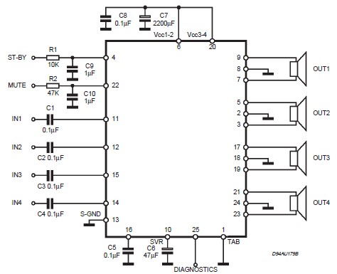
This circuit illustrates a car audio amplifier utilizing the TDA7381 integrated circuit (IC). The TDA7381 audio amplifier IC allows for the design of a straightforward 4x25 watts car radio. The TDA7381 is a high-performance audio amplifier designed specifically for automotive...
Amplifying weak radio signals presents the challenge of also amplifying noise. The ability to receive signals is contingent on the level of background noise, which can include man-made interference or static. In this design, the RF signal first encounters...
.gif)
This article includes a list of references, but its sources remain unclear due to insufficient inline citations. More precise citations are needed to improve this article. Valves, also known as vacuum tubes, exhibit very high input impedance (nearly infinite...
In this circuit we use the 2SK1058 and the 2SJ162 Mosfets. This could be avoided by a fairly simple bootstrapping circuit, but the improvement in maximum output may be just a fraction of a dB, depending on the supply...
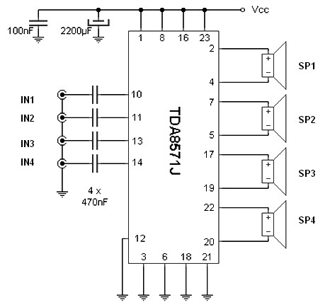
The integrated audio TDA8571J, designed for automotive applications, allows for the expansion of car radio sound or the connection of a portable MP3 player. Internally, the chip contains eight operational amplifiers set in a bridge configuration, enabling each speaker...
The amplifier circuit is designed for a center frequency of 225 MHz, with a bandwidth of 50 MHz at 1 dB, low input voltage standing wave ratio (VSWR) in a 75-ohm system, and a gain of 24 dB. Three...