
8051 flash programmer

The programmer facilitates both parallel and SPI programming, enhancing user convenience. It features a powerful Windows-based graphical user interface (GUI) that simplifies the programming process. The circuit diagram for the stand-alone SPI programmer indicates that power is supplied to the interface via the PC USB port, which can deliver a maximum current of 100mA. A standard USB cable can be utilized; by cutting the connector from one end and attaching a crimp shell connector, the red wire will provide 5V while the black wire serves as the ground (0V). The 74HCT541 integrated circuit (IC) is employed to isolate and buffer the signals from the parallel port. It is essential to use the HCT type IC to ensure compatibility with 3V parallel ports.
For the microcontroller, a 40-pin zero insertion force (ZIF) socket is recommended. This programmer circuit is capable of programming the 89S series devices as well as AVR series devices that are pin-compatible with the 8051, such as the 90S8515. For other AVR series devices, users may create an adapter board for 20, 28, and 40-pin configurations. The pin numbers indicated in brackets correspond to the PC parallel port connector. It is critical to avoid programming the RSTDISBL fuse in the ATmega8, ATtiny26, and ATtiny2313; doing so will disable further SPI programming, necessitating the use of a parallel programmer to re-enable it.
The 8051 Programmer circuit is designed for versatility and ease of use, making it an essential tool for developers working with a variety of Atmel microcontrollers. The integration of a user-friendly GUI allows for efficient programming, while the circuit design ensures that it can operate effectively across different voltage levels, accommodating both traditional and modern microcontroller architectures. The use of the 74HCT541 IC plays a crucial role in maintaining signal integrity, which is vital for successful programming operations. The inclusion of a ZIF socket facilitates easy insertion and removal of microcontrollers, streamlining the programming process. Overall, this programmer offers a comprehensive solution for interfacing with a range of microcontroller devices, enhancing development workflows in embedded systems design.Sometimes, you may keep a part of application code in the Flash/EPROM version of the 8031 and remaining part in an EPROM (in an expanded system). Time has come to introduce another useful tool, 8051 Programmer. This Programmer supports the devices in the 8031 family of Atmel, AT89SXX, and its AVR microcontroller AT90SXXXX series Controllers.
The programmer supports both parallel and SPI programming for your convenience. A powerful window`s based GUI facility makes your programming task an easy one. The circuit diagram of the stand-alone spi programmer, the power to the interface is provided by the PC USB port which can supply a max of 100mA current. Get a cheap USB cable, cut the cable other end connector and attach a crimp shell connector to this end, red wire is 5V and black is 0V.
The 74HCT541 ic isolate and buffer the parallel port signals. It is necessary to use the HCT type ic in order to make sure the programmer should also work with 3V type parallel port. For the u-controller a 40 pin ZIF socket can be used. This programmer circuit can be use to program the 89S series devices and the AVR series devices which are pin compatible to 8051, like 90S8515.
For other AVR series devices the user can make an adapter board for 20, 28 and 40 pin devices. The pin numbers shown in brackets correspond to PC parallel port connector. Also make sure do not program the RSTDISBL fuse in ATmega8, ATtiny26 and ATtiny2313 otherwise further spi programming is disable and you will need a parallel programmer to enable the 🔗 External reference
Related Circuits

Q1 is a phototransistor that is normally illuminated by a beam of light. When the beam is interrupted, pin 1 of U1A goes high, which forces pin 4 of U2B low. Consequently, capacitor C2 discharges through resistors R2 and...
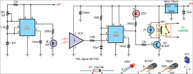
This circuit serves as an alternative to the infrared (IR) beam break detector featured in the June 2009 issue of Silicon Chip. It utilizes a standard IR receiver IC, such as the Jaycar ZD-1942, to minimize sensitivity to ambient...

This is a very basic circuit for flashing one or more LEDs and also to alternately flash one or more LEDs. It uses a 555 timer setup as an astable multivibrator with a variable frequency. With the preset at...
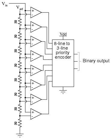
Also known as the parallel A/D converter, this circuit is the simplest to understand. It consists of a series of comparators, each comparing the input signal to a unique reference voltage. The outputs of the comparators connect to the...

A 555 timer, referred to as IC1, controls a 4017 CMOS decade counter. The first four outputs of the 4017 drive a CA3079 zero-voltage switch. Pin 9 of the CA3079 is utilized to inhibit output from pin 4, which...
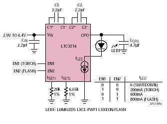
An ultralow dropout current source maintains accurate LED current at very low ILED voltages. Automatic mode switching optimizes efficiency by monitoring the voltage across the LED current source and switching modes only when ILED dropout is detected. The LTC3216...