
LED Flasher with 555

The described circuit employs a 555 timer IC configured in an astable mode, which is ideal for generating a square wave output. This output can be used to drive one or more light-emitting diodes (LEDs) for visual signaling. The frequency of the blinking can be adjusted by changing the timing components, specifically the resistor and capacitor values. In the standard configuration, a capacitor of 10µF and appropriate resistor values yield a flashing rate of approximately 2 Hz (half a second on, half a second off). By increasing the capacitor value to 22µF, the flashing rate can be reduced to about 1 Hz (one second on, one second off), providing flexibility in the visual output speed.
For alternating flashing, the circuit allows for the addition of a second LED. This is accomplished by connecting an additional LED in series with a 330-ohm resistor to designated points on the circuit board, enabling both LEDs to flash alternately. The 555 timer's ability to source or sink up to 200mA of current permits the connection of multiple LEDs in parallel, facilitating a maximum of approximately 18 LEDs for both the standard and alternating configurations. This results in a total potential of 36 LEDs when utilizing the alternating flasher feature.
The schematic for this circuit would typically include the 555 timer, resistors for timing, a capacitor for frequency adjustment, and the LEDs with their respective current-limiting resistors. Proper attention should be given to the power supply to ensure it can handle the total current drawn by the LEDs. Additionally, the circuit layout should minimize interference and ensure stable operation of the 555 timer.This is a very basic circuit for flashing one or more LEDS and also to alternately flash one or more LEDs. It uses a 555 timer setup as an astable multivibrator with a variable frequency. With the preset at its max. the flashing rate of the LED is about 1/2 a second. It can be increased by increasing the value of the capacitor from 10uF to a higher value. For example if it is increased to 22uF the flashing rate becomes 1 second. There is also provision to convert it into an alternating flasher. You just have to connect a LED and a 330ohm as shown in Fig.2 to the points X and Y of Fig.1. Then both the LEDs flash alternately. Since the 555 can supply or sink in upto 200mA of current, you can connect upto about 18 LEDS in parallel both for the flasher and alternating flasher (that makes a total of 36 LEDs for alternating flasher). 🔗 External reference
Related Circuits
More: An electronic schematic is a representation of the components and connections within an electronic circuit. It serves as a blueprint for constructing electronic devices, allowing engineers and technicians to visualize how components interact and function together. The schematic...
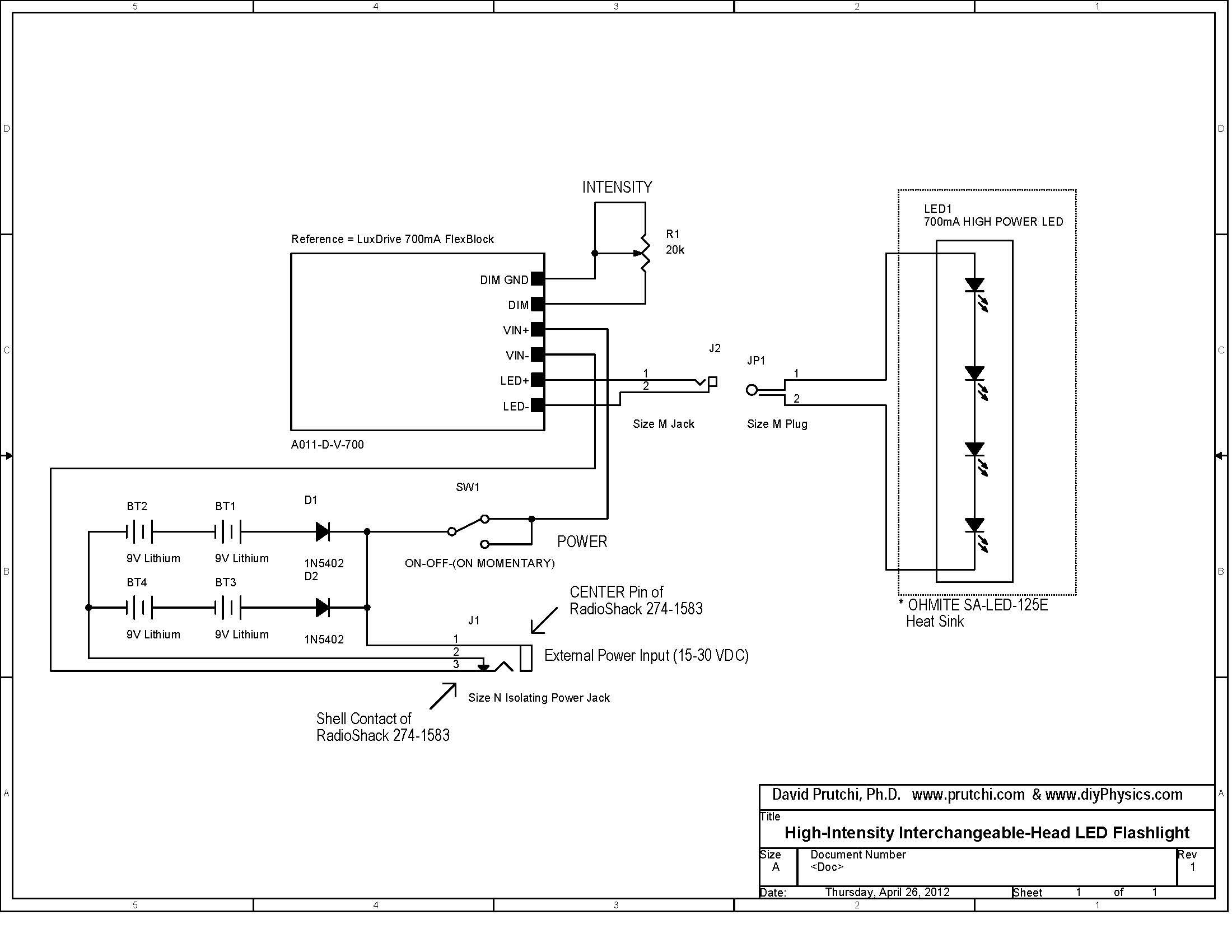
Build a 10W LED flashlight that features swappable UV, IR, and visible light heads. This flashlight is designed to complement a photographer's toolkit for applications such as light painting, infrared illumination, UV-reflected photography, or UV fluorescence photography. The flashlight...
Efficient automatic solar garden lights circuit with minimal components. The advantage is that it operates completely automatically, with the solar panel serving as a light detector. The efficient automatic solar garden lights circuit is designed to provide illumination using renewable...
The object of Quick Draw is to test your reaction time against your opponent's. A third person acts as a referee and begins the duel by pressing S1, which lights LED1. Upon seeing LED1 go on, you try to...
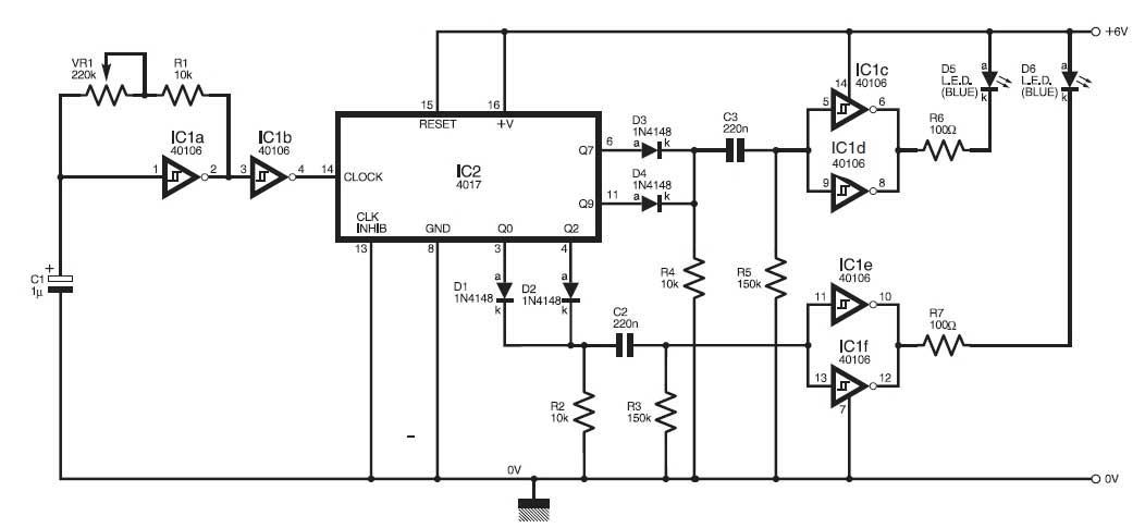
This circuit simulates the flashing lights of a police car, similar to those seen on British police vehicles. The operational amplifier IC1a functions as a square wave oscillator, with an adjustable frequency controlled by the variable resistor VR1 to...
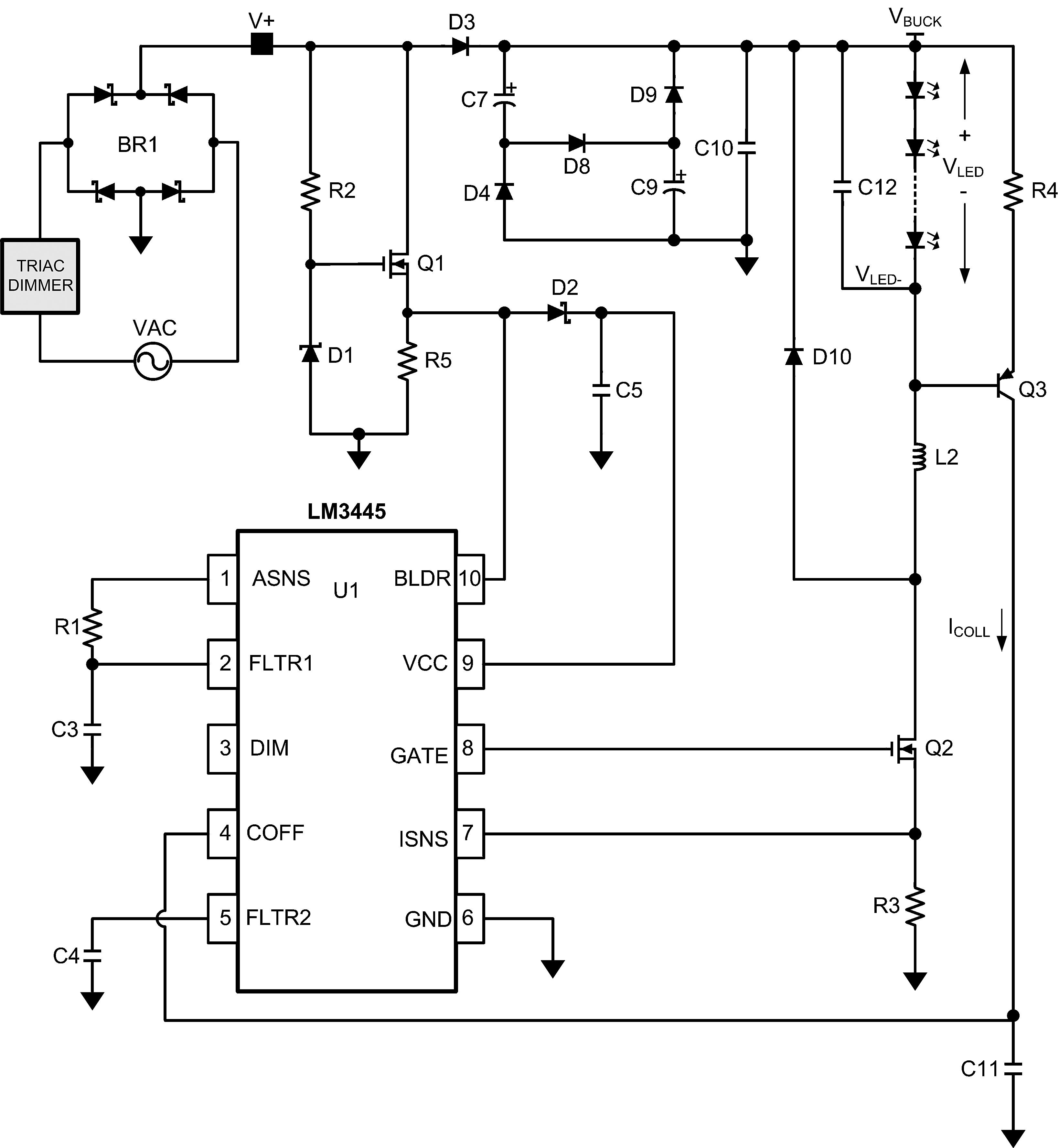
The LM3445 is an adaptive constant off-time AC/DC buck (step-down) constant current controller designed for compatibility with triac dimmers. The LM3445 is a specialized integrated circuit that functions as a constant current controller in AC/DC applications, particularly suited for LED...