
Sequential flasher
In addition, switching at the zero crossing significantly reduces Radio-Frequency Interference (RFI). It is important to note that the CA3079s are directly driven from the 117-volt AC power line, necessitating caution during implementation.
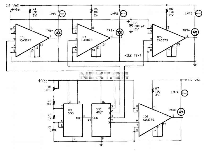
The circuit employs a 555 timer configured in astable mode, generating a continuous square wave signal. This signal is fed into the clock input of the 4017 decade counter, which counts the pulses and sequentially activates its outputs. The first four outputs of the 4017 are connected to the control inputs of the CA3079 zero-voltage switches, which are designed to control the TRIACs responsible for the lamp operation.
The CA3079 zero-voltage switch is a critical component that ensures the TRIACs are activated only when the AC voltage is near zero, effectively reducing stress on the lamps and extending their operational life. The inhibition feature provided by pin 9 allows for precise control over the output, enabling the user to disable specific outputs when necessary.
The timing characteristics of the circuit, with a pulse width of 120 microseconds and a frequency of 120 Hz, are suitable for applications requiring efficient switching of resistive loads such as incandescent lamps. By minimizing the inrush current and switching at the zero crossing, the circuit not only enhances the lifespan of the lamps but also mitigates the potential for RFI, making it a reliable solution for lighting control in various environments. Safety precautions should be strictly observed when working with the CA3079, given its direct connection to the high-voltage AC power line.A 555 timer, IC1, drives a 4017 CMOS decade counter. Each of the 4017's first four outputs drives a CA3079 zero-voltage switch. Pin 9 of the CA3079 is used to inhibit output from pin 4, thereby disabling the string of pulses that IC normally delivers. Those pulses occur every 8.3 ms, i.e., at a rate of 120 Hz. Each pulse has a width of 120 jis. Due to the action of the CA3079, the lamps connected to the TRI-AC's turn on and off near the zero crossing of the ac waveform.
Switching at that point increases lamp life by reducing the inrush of current that would happen if the lamp were turned on near the high point of the ac waveform. In addition, switching at the zero crossing reduces Radio-Frequency Interference (RFI) considerably. CAUTION: The CA3079's are driven directly from the 117-volt ac power line, so use care. 🔗 External reference
Related Circuits
This is a 220V LED flasher circuit designed as a reliable alternative to thermally activated switches used for flashing Christmas tree lamps. It is a cost-effective and easy-to-assemble circuit. The components include R1 (100K), R2 (1K), R5 (1K), R3...
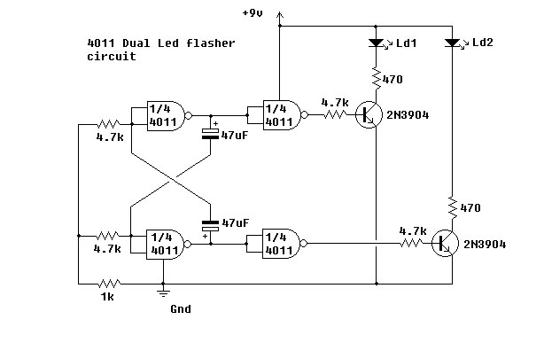
This simple circuit utilizes NAND gates to alternately flash two LEDs. The two 47µF capacitors set the flashing frequency. It is advisable to include a decoupling capacitor across the power supply. The circuit was constructed using the specified components...
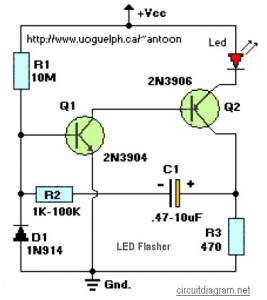
This circuit is designed to flash a high-brightness red LED (5000 mcd), making it suitable for use in fake car alarms or other devices intended to attract attention. The specific values of the components are not critical, allowing for...
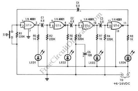
This schematic diagram illustrates a ring-around LED flasher circuit. The circuit operates by turning off two LEDs while activating the other two, continuing this pattern until the timing cycle reverses. The ring-around LED flasher circuit is designed to create a visually...
This circuit functions as a phone message flasher, providing an alternative method to alert users of an incoming call. When the phone rings, a high line voltage is activated. The phone message flasher circuit is designed to enhance the traditional...
This may be the simplest LED flasher circuit you can build, with the notable exclusion of LEDs with integrated flashing circuits. This might be a good replacement for the LM3909 in some applications. Take a close look. Only the...
Warning: include(partials/cookie-banner.php): Failed to open stream: Permission denied in /var/www/html/nextgr/view-circuit.php on line 713
Warning: include(): Failed opening 'partials/cookie-banner.php' for inclusion (include_path='.:/usr/share/php') in /var/www/html/nextgr/view-circuit.php on line 713