
89Sxx Development Board
There are some 89Sxx development board, here is another one. I have designed this single side development board to be used as a tool for learning MCS-51 Microcontrollers, and for easy microcontroller project development.
The 89Sxx development board features:
89Sxx 40-DIL based design, 89S51/52/53
In System Programming (ISP) through the 6-pin header
RS-232 and RS-485 serial port (shared pin) for communicating with serial devices like PC
HD44780 compatible alphanumeric LCD connectivity with backlight control
4 on-board tact switch
16 general purpose IO port pins on 5x2 header (Port0 and Port2)
24Cxx I2C EEPROM
DS1302 serial Real Time Clock (RTC) with battery backup
On-board supply rectifier and voltage regulator
Single sided PCB design
The project shows 89Sxx Development Board for remote control and monitoring. The system consists of 89S52 as main processor and mobile-phone (GSM modem) for remote control or monitoring over cellular network. Features of the system are as follows.
Features of the system are as follows:
8 ch input (Port0) and 8 ch output (Port2)
auto-send message on input changing/alarm, input changing mode: LO-HI, HI-LO
switch output command by group or independently
status request parameter by sending SMS command
download some simple text script for time programmable output
This circuit connects to the serial port featured by many cellular phones. Its function is to provide an input and an output port capable of being remotely controlled using another mobile. Control takes place by means of sending SMS (Short text Messages Service). When the mobile receives a predefined text message, the circuit automatically recognizes it as a command, and switches the output accordingly.
The device can be used to notify the status of the input port, sending automatically a message every time the input changes. To know input status at any time, the device can send back an SMS describing the status of the input, as a response to a request message.
Communication between board and mobile-phone (modem): rxgsm (P3.3, RX from gsm), txgsm (P3.4, TX to gsm) in TTL level. To start interfacing with, similar to modems, GSM cellular phones can accept AT commands (more precisely an extension of the AT command set).
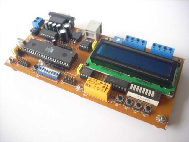
The described hardware block utilizes the 89Sxx microcontroller architecture, specifically designed for educational and project development purposes. The 89Sxx microcontroller serves as the central processing unit, interfacing with various peripherals and components to facilitate a wide range of applications. The schematic includes a 4-bit interface for an HD44780 compatible LCD, which supports a 16x2 character display with backlight functionality, enhancing visibility in low-light environments.
Port1 is designated as the data bus for the LCD, while Port0 and Port2 are configured as general-purpose input/output (GPIO) pins, allowing for versatile connectivity with external devices. Port0 is connected to a DIP switch for manual input selection, and specific pins (P0.0 and P0.1) are connected to opto-isolated inputs for improved signal integrity and protection against high voltages.
Serial communication is facilitated through UART on Port3, with dedicated pins (P3.0 and P3.1) handling RX and TX respectively. Additionally, P3.2 is allocated for RS-485 control direction, enabling robust communication over longer distances. The GPIO capabilities extend to P3.3 and P3.4, which are also used for interfacing with a GSM modem, allowing for remote control and monitoring applications.
The board incorporates an I2C EEPROM (24Cxx) for non-volatile data storage, and a DS1302 real-time clock (RTC) with battery backup to maintain accurate timekeeping even during power outages. A voltage regulator and rectifier circuit ensure stable power supply to the microcontroller and peripherals.
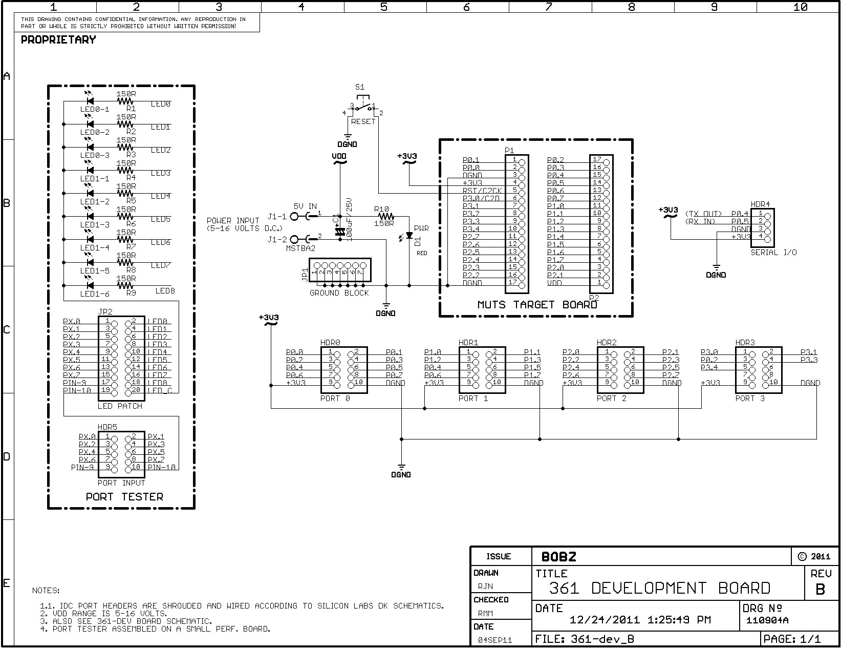
This development board is particularly suited for projects involving remote monitoring and control through SMS, leveraging the GSM modem for communication. The system's architecture allows for multiple input and output channels, enabling complex control logic and automation tasks. Furthermore, the ability to send status updates via SMS enhances the system's functionality, providing real-time feedback to users. Overall, the described hardware block presents a comprehensive solution for learning and implementing microcontroller-based projects.The hardware block is shown in Figure 1. The MCU is 89Sxx microcontroller. And the complete hardware schematic is shown in Figure 2. Port1 is used as data-bus for LCD (4-bit interface, PCB lay-out for 16x2 character with backlight), on-board tact switch and connection for In System Programming (ISP) Port0 and Port2 as general purpose IO, are available for interfacing external devices. Port0 is connected with DIP switch, and also P0.0 and P0.1 are connected with opto-isolated input Port3, P3.0 and P3.1 are being used for serial communication UART, P3.2 for RS-485 control direction.
P3.3 and P3.4 are serving as general purpose IO port pins. Another pins for communicating with serial chip, EEPROM, RTC and serial shift register (LED array indicator) There are some 89Sxx development board, here is another one. I have designed this single side development board to be used as a tool for learning MCS-51 Microcontrollers, and for easy microcontroller project development. The 89Sxx development board features : 89Sxx 40-DIL based design, 89S51/52/53 In System Programming (ISP) through the 6-pin header RS-232 and RS-485 serial port (shared pin) for communicating with serial devices like PC HD44780 compatible alphanumeric LCD connectivity with backlight control 4 on-board tact switch 16 general purpose IO port pins on 5x2 header (Port0 and Port2) 24Cxx I2C EEPROM DS1302 serial Real Time Clock (RTC) with battery backup On-board supply rectifier and voltage regulator Single sided PCB design The project shows 89Sxx Development Board for remote control and monitoring.
The system consists of 89S52 as main processor and mobile-phone (GSM modem) for remote control or monitoring over cellular network. Features of the system are as follows. Features of the system are as follows: 8 ch input (Port0) and 8 ch output (Port2) auto-send message on input changing/alarm, input changing mode : LO-HI, HI-LO switch output command by group or independently status request parameter by sending SMS command download some simple text script for time programmable output This circuit connects to the serial port featured by many cellular phones.
Its function is to provide an input and an output port capable of being remotely controlled using another mobile. Control takes place by means of sending SMS (Short text Messages Service). When the mobile receives a predefined text message, the circuit automatically recognizes it as a command, and switches the output accordingly.
The device can be used to notify the status of the input port, sending automatically a message every time the input changes. To know input status at any time, the device can send back a SMS describing the status of the input, as a response to a request message.
Communication between board and mobile-phone (modem) : rxgsm (P3.3 , RX from gsm), txgsm (P3.4 , TX to gsm) in TTL level. To start interfacing with, similar to modems, GSM cellular phones can accept AT commands (more precisely an extension of the AT command set).
🔗 External reference
Related Circuits
This article aims to utilize an old PC as a simple controller. Many outdated PCs, such as the 8088, 8086, 80286, 80386, or even 80486, have become obsolete systems. This design employs an 8-bit LPT printer parallel data port...
This design is based on the work of Andrew Bruno, referred to as "bruno-if." The contribution involved providing Postscript files for a Printed Circuit Board. The circuit is relatively old, dating back to the NMEA-0180 and NMEA-0182 standards. It...
The following details the design, construction, operation, and application of the Multiple Target Development System (MUTS). The MUTS includes a Target board that connects to a Silicon Laboratories (SL) Debug Adapter for programming the Target board using the SL...
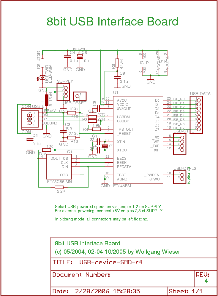
The objective was to create a compact USB interface board that can be easily connected to microcontroller boards. It is designed to support both USB-powered and externally-powered operation. The number of external components has been minimized, although there are...
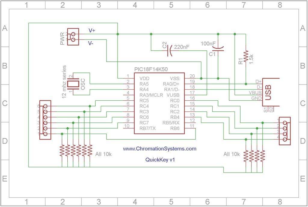
Quick Key Adapter, 10 Button HID Keyboard. This document outlines the process of creating a USB-connected Human Interface Device (HID) keyboard featuring 10 button inputs. The Quick Key Adapter is designed to facilitate user interaction through a compact keyboard interface....
The layout control motherboard is designed to facilitate the management of various sections of a layout. It features a microcontroller that connects to the MRNet bus and multiple slots for inexpensive control and sensor boards. All control and sensor...