
relay driver board project
This schematic describes a practical approach to repurposing outdated PC hardware into a functional relay controller. The design leverages the LPT port for data output, allowing the control of multiple relays through a straightforward interface. The use of optocouplers ensures electrical isolation, thus protecting the sensitive components of the PC from potential damage due to high-voltage spikes from the relay circuit.
The circuit's architecture is based on a modular design, where each channel operates independently, enhancing reliability and ease of troubleshooting. The inclusion of diodes for transient protection is essential in preventing back EMF from damaging the driving transistors. The selection of high-power transistors ensures that the relays can be activated without risking overheating or failure.
In terms of component selection, the use of common, readily available parts like the 7824 voltage regulator and the 1N4007 diodes simplifies sourcing and assembly. The recommended relay specifications ensure compatibility with various AC loads, making the controller versatile for different applications. Additionally, the optional components, such as the heatsink and power switch, provide further customization and efficiency enhancements.
Overall, this design provides a cost-effective solution for controlling devices using legacy PC technology, making it an excellent project for electronics enthusiasts and those looking to extend the life of older computing hardware.This article means to utilize your old PC to be come a simple controller. Many old PC like 8088 type, 8086, 80286, 80386, or even 80486 already become an obsolete systems. This board using 8-bits of LPT printer parallel data port (DP) to activate the relays. LPT printer parallel port also have 4-bits additional port (PC) which can be utilized too. But this is not implemented in this design, because in my opinion, 8-bits are more than enough, and beside that this size (1 byte) fit each of 8255 PPI port if we want to interface it too. The basic is the same for all the eight channels. To protect the LPT port from damage, I use optocoupler to isolated the PC side (+5V) and relay circuit (+24V).
You can change the relay voltage type to +12V or even +6V if you can find one. This type of optocoupler, PC914 can be replaced with another type like 4N series (4N22 ~ 4N28, 4N35, 4N47 ~ 4N49, etc. ). Using a common driver combination, transistor Q1 ~ Q8 (hi-power) to drive the relays. D1 ~ D8 use to protect the transistor from any transient current when the relay is in the off state. The resistor values are chosen to make transistors get full enough saturated when it is on. This common driver also can be change using IC driver like: ULN2002 ~ ULN2004 types. Each package contain 6-bits line drivers. So you need 2 of this IC, but one does not maximize. If you use PC port, than this IC can be utilized. A good alternative. Note that, for the relays, it must be stand the high voltage and current (big power) if you want to use it to drive any equiptment from the AC line.
Find a good ones with a high rating output. Careful about the hi-voltage line on the PCB. R1 ~ R16 = 10k. 16 pcs R17 ~ R24, R33 = 1k5. 9 pcs R25 ~ R32 = 1k. 8 pcs C1 = 2200 uF/50V (elco). 1 pcs C2 = 1000 uF/25V (elco). 1 pcs D1 ~ D12 = 1N4007. 12 pcs Led1 ~ Led9 = Red Led (3 mm). 9 pcs IC1 = 7824 (voltage regulator). 1 pcs Q1 ~ Q8 = C1061 (transistor). 8 pcs OP1 ~ OP8 = PC914 (optocoupler). 8 pcs RL1 ~ RL8 = 24V relay PCB type (hi-power output, 5A/220V-AC). 8 pcs CON1 = DB-25 socket (female, PCB type, LPT connector). 1 pcs Optional CON2 = power connector. 1 pcs OUT-1 ~ OUT-8 = 2-pairs of terminal strip. 8 pcs Transformer = 15V with CT/1A or 30V-AC/1A. 1 pcs Optional on/off switch for power supply. 1 pcs Optional LPT parallel port cable (3 m). 1 pcs Optional little heatsink for voltage regulator. 1 pcs 🔗 External reference
Related Circuits
Most individuals seeking to modify and enhance their Spectrum often focus on the keyboard as a primary area for improvement. However, a straightforward replacement requires opening the computer, which can be discouraging for two main reasons. Firstly, this action...
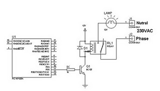
A relay can be controlled using a PIC microcontroller. The circuit illustrates how to control a single relay with the PIC 16F628. When the RB5 port of the PIC is set to high, the relay will activate. This circuit...

A high brightness LED evaluation board has been developed using the Fairchild Semiconductor FAN7554D PWM controller. The evaluation board for high brightness LEDs incorporates the Fairchild Semiconductor FAN7554D PWM controller, which is designed to provide efficient power management and precise...
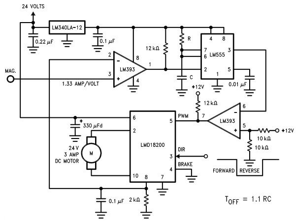
The LMD18200 3A H-Bridge, designed by National Semiconductors, can be used to create a simple motor controller electronic project suitable for motion control applications. This component is ideal for driving both DC and stepper motors, accommodating peak output currents...

It is essential to ensure that none of the light bulbs on the vehicle are burnt out, particularly the turn signal lights, brake lights, and dashboard indicator lights. Malfunctions can occur when bulbs are burnt out. Utilizing the exterior...
This is a video showcasing a test flight of the Quad Rotor Observer (QRO) v8, which is equipped with the FCWii board, Wii Motion Plus gyroscopes, and Nunchuk accelerometers. The Quad Rotor Observer (QRO) v8 is an advanced quadcopter designed...