
8V DC Power Supply With Over Voltage Protection

The 8V DC power supply circuit is designed with several critical components to ensure reliable operation and protection for sensitive electronic equipment. The full-wave rectifier converts the incoming AC voltage into a pulsating DC voltage, which is then smoothed by filtering capacitors to reduce ripple. The three-terminal voltage regulator (REG1) stabilizes the output voltage at 8V, providing a consistent power supply to the load.
The use of a Schottky diode (D3) is significant due to its low forward voltage drop, which minimizes power loss and enhances efficiency. The 500mA fuse serves as a primary protection mechanism, preventing excessive current from damaging the circuit components.
The inclusion of LED indicators (LED2 and LED3) provides visual feedback to the user regarding the operational status of the power supply. Yellow LED2 signifies that unregulated voltage is present, while green LED3 confirms that the voltage has been regulated to the desired level.
The "crowbar" protection mechanism is an essential safety feature. Zener diode ZD1 is calibrated to activate at a predetermined over-voltage threshold. When triggered, it conducts and applies a gate voltage to SCR1, which acts as a switch to short the output and blow the fuse, thereby disconnecting the load and preventing damage from excessive voltage.
In addition, ZD2 serves as a backup protection measure, ensuring that even if the primary crowbar circuit fails, the system remains safeguarded against over-voltage conditions.
The test function provided by switch S1 is crucial for maintenance and troubleshooting. By allowing the operator to simulate an over-voltage condition, the functionality of the crowbar circuit can be verified without risking damage to the connected load. The visual indication through LED1 when the SCR is triggered further aids in diagnostics.
Overall, this power supply circuit combines effective voltage regulation and robust protection mechanisms, making it suitable for high-performance electronic applications.This 8V DC power supply was designed for use with an expensive piece of electronic equipment. It features full over-voltage protection as a precaution against regulator failure, either in the supply itself or inside the equipment it is powering. The circuit uses a conventional full-wave rectifier, followed by a 3-terminal voltage regulator (REG1)
with appropriate filtering. When power is applied and switch S1 is in the "Run" position, REG1s output is fed to the load via a 500mA fuse and Schottky diode D3. This also lights LED2 (yellow) and LED3 (green), which respectively indicate the presence of the unregulated and regulated voltages.
D3 is there to protect the circuit against external voltage sources (eg, charged capacitors). A "crowbar" circuit comprising ZD1 and SCR1 provides the over-voltage protection. It works like this: if a fault develops (eg, REG1 short circuit) which causes the output voltage to rise above 9. 1V, ZD1 turns on and applies a voltage to the gate of SCR1. If the voltage then continues to rise, SCR1 turns on (at about 10V) and "blows" the fuse. Zener diode ZD2 provides emergency over-voltage protection in case the "crowbar" circuit develops a fault.
Switch S1 is provided so the operator can occasionally test the "crowbar" function. When S1 is switched to the "Test" posi tion, the load is disconnected by S1b and the unregulated supply voltage is applied by S1a to the "crowbar" circuit, thus causing it to trigger. When this happenS, LEDs 2 & 3 (green and yellow) extinguish and LED1 (red) lights to indicate that the SCR has triggered.
The SCR turns off again when S1 is switched back to the "Run" position. 🔗 External reference
Related Circuits
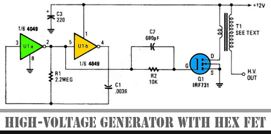
The schematic diagram below illustrates a high voltage generator circuit. This circuit employs a 4049 hex inverter configured as an oscillator, and it can utilize an ignition transformer from an automotive engine. A fly-back transformer may also be suitable....
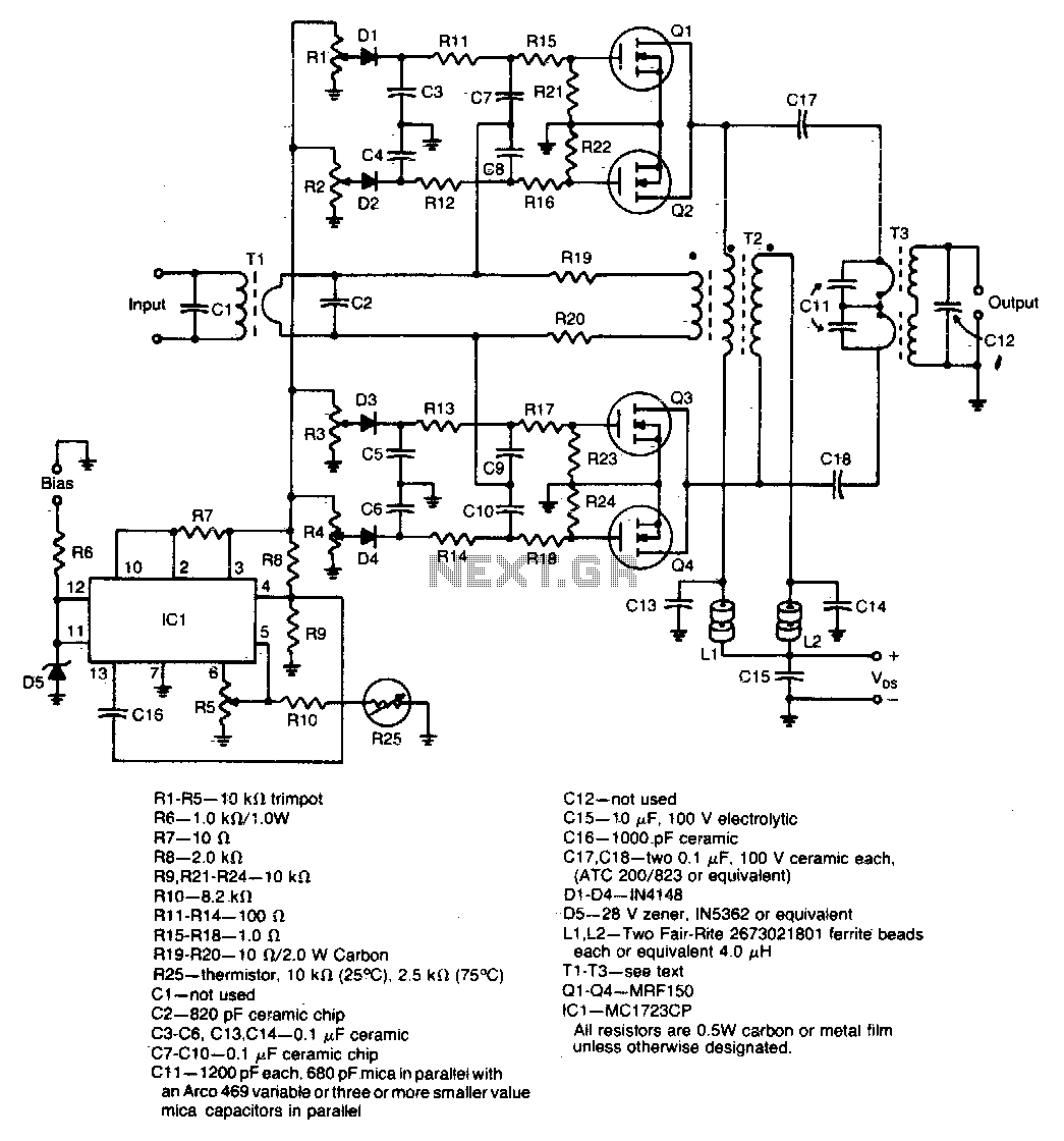
A unique push-pull parallel circuit utilizes four MRF150 RF power FETs connected in parallel at relatively high power levels. Supply voltages ranging from 40 to 50 Vdc can be employed, contingent on the linearity requirements. The bias for each...
If a negative supply is required for an operational amplifier or if a negative bias voltage is needed while operating from a single supply voltage, such as in battery applications. To generate a negative supply voltage from a single positive...
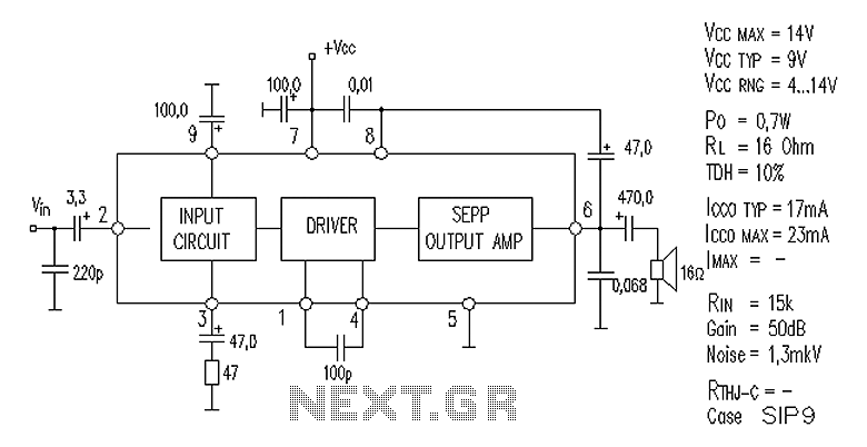
AN7112 power amplifier circuit diagram The AN7112 is a power amplifier designed for audio applications, capable of delivering high output power while maintaining high fidelity. The circuit diagram typically includes essential components such as transistors, resistors, capacitors, and a...
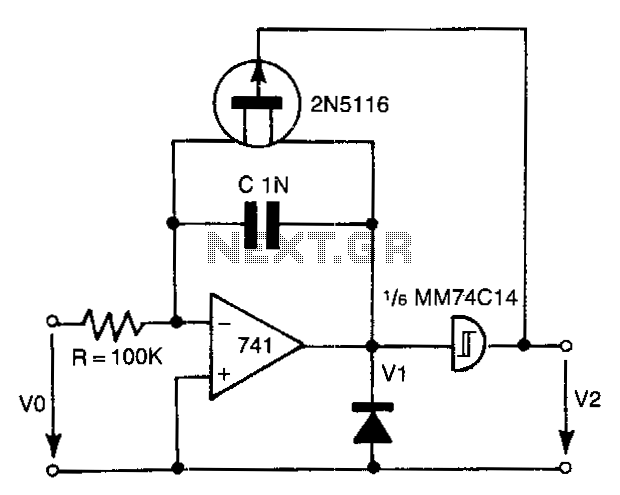
The 741 operational amplifier integrator signal is input into the Schmitt trigger of an inverter. When the signal reaches the positive-going threshold voltage, the inverter's output switches to zero. This output directly controls the FET switch. With a gate...
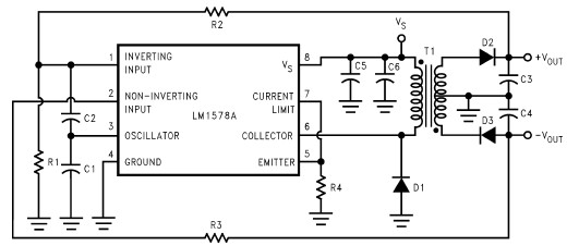
This RS232 power supply circuit diagram is a simple RS-232 line driver power supply that operates from an input voltage as low as 4.2V and delivers an output of ±12V at ±40 mA with an efficiency of better than...