
9 Second LED Timer and Relay

This circuit utilizes a 555 timer configured in astable mode to generate a clock pulse. The output from the timer is fed into a 4017 decade counter, which counts the clock pulses and drives a series of 10 LEDs for visual indication. The reset switch allows for the manual resetting of the counter, ensuring that the sequence begins anew when the switch is activated.
The 555 timer operates by charging a timing capacitor through a resistor, which establishes the timing intervals. The capacitor's charge voltage determines when the output switches states, and in this case, it is designed to create a 1-second pulse. The decade counter increments its count with each pulse received at its clock input (pin 14) and only operates when enabled by pin 13 being low.
Upon reaching the 9th count, the outputs at pins 11 and 13 of the 4017 become high, which not only stops the counting process but also activates a relay that can control external devices or circuits powered by 12 volts. The visual feedback provided by the 10 LEDs serves as an effective indicator of the countdown process, allowing users to observe the status of the circuit at a glance.
To modify the delay time, adjustments can be made to the timing capacitor or the resistors connected to the 555 timer. Increasing the capacitance or resistance will result in a longer delay, offering flexibility in applications where different timing requirements are necessary. This circuit is suitable for various timing applications where visual indication and relay control are required.This circuit provides a visual 9 second delay using 10 LEDs before closing a 12 volt relay. When the reset switch is closed, the 4017 decade counter will be reset to the 0 count which illuminates the LED driven from pin 3. The 555 timer output at pin 3 will be high and the voltage at pins 6 and 2 of the timer will be a little less than the lower t
rigger point, or about 3 volts. When the switch is opened, the transistor in parallel with the timing capacitor (22uF) is shut off allowing the capacitor to begin charging and the 555 timer circuit to produce an approximate 1 second clock signal to the decade counter. The counter advances on each positive going change at pin 14 and is enabled with pin 13 terminated low.
When the 9th count is reached, pin 11 and 13 will be high, stopping the counter and energizing the relay. Longer delay times can be obtained with a larger capacitor or larger resistor at pins 2 and 6 of the 555 timer.
🔗 External reference
Related Circuits
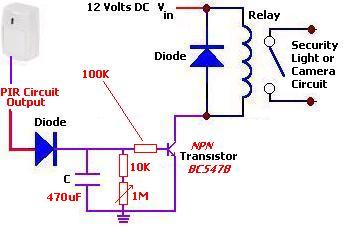
The following circuit illustrates a PIR Sensor Timer Circuit Diagram. Features include a simple design, enhanced accuracy, and efficiency. Components involved are a diode, among others. The PIR (Passive Infrared) Sensor Timer Circuit is designed to detect motion through infrared...
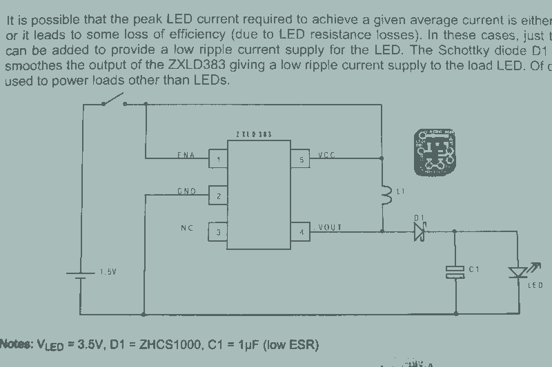
It may seem that due to the numerous flashlight projects undertaken, there is a significant collection of lights. The inductor can be altered to set the current level, but the total current fluctuates with the battery supply, decreasing as...
A tiny sandwich flag connected perpendicular to the motor spindle aids observation of how long it takes to complete one full rotation. This worked initially, as each burst from the capacitor barely moved the flag 1/4 of a rotation....
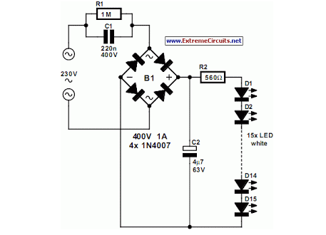
An array of white LEDs can serve as an effective small lamp for the living room. LED lamps are commercially available. LED arrays are increasingly popular for providing ambient lighting in residential spaces. The use of white LEDs in a...
This timer is designed primarily to turn off a portable radio after a set duration. This feature allows users to relax on the beach or in a hammock, confident that the device will automatically power down after a specified...
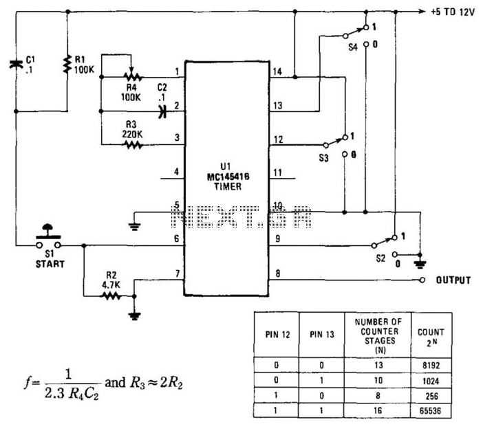
By utilizing an RC oscillator and a programmable divider, this counter can operate for extended periods. The interval oscillator functions at a frequency determined by specific component values: for instance, with R1 = 390 kΩ and C2 = 10...