
915-MHz antenna monopole
The Tab antenna design is characterized by its compact structure, which is essential for applications requiring minimal space without compromising performance. The folded monopole configuration allows for a significant reduction in size while maintaining effective radiation characteristics. The inverted L shape, formed by the downward bend, optimizes the antenna's impedance matching, transforming the inherent 12.5Ω radiation resistance to a more standard 50Ω, which is suitable for most RF applications.
Soldering the antenna perpendicular to a printed circuit (PC) board or integrating it directly into the PCB layout provides flexibility in design. This placement can enhance the antenna's performance by minimizing the ground plane effects and optimizing the radiation pattern. The corner placement on the PCB is particularly advantageous as it can help in achieving a more uniform radiation pattern and reduce potential interference from other components.
The folded section of the Tab antenna not only aids in impedance transformation but also plays a crucial role in harmonic suppression. The design effectively suppresses second harmonics, which is vital for maintaining signal integrity in communication systems. Furthermore, the incorporation of an open stub near the base of the antenna provides additional third-harmonic suppression, further enhancing the antenna's performance and reducing unwanted emissions.
Advanced modeling techniques, such as NEC-2, are employed to analyze the antenna's performance under various conditions. This modeling takes into account the sensitivity of the antenna dimensions, allowing for optimization of harmonic suppression and overall efficiency. It is important to note that while NEC models assume a vacuum environment, the Tab antenna's actual performance must consider the dielectric properties of the FR-4 material used in its construction. This inclusion is critical for accurately predicting the antenna's behavior in real-world applications, ensuring reliable performance across the intended frequency range.The Tab antenna is a folded monopole that you miniaturize by forming it into an inverted L with a downward bend at the end (Figure 1). You can solder it perpendicular to a pc board or build it as part of a pc board and place it at a corner.
The folded section transforms the 12.5Ω radiation resistance to 50Ω and provides second-harmonic suppression. Third-harmonic suppression comes from an open stub near the base of the antenna. Detailed NEC-2 modeling explores the sensitivity to changes in the dimensions and optimized harmonic suppression. Because NEC models wire antennas in a vacuum and the Tab antenna is built on FR-4, you must incorporate the dielectric properties of the diel
🔗 External reference
Related Circuits
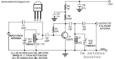
The coil L2 is tapped at the first turn from the ground lead side and is similar to coil L1, but consists of only three turns. The pin configuration of the transistor 2SC2570 is illustrated in the FM antenna...
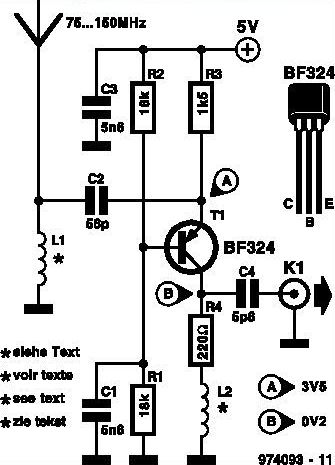
This inexpensive FM radio receiver antenna booster utilizes the BF324 TO92 style PNP transistor in a grounded-base configuration. The circuit can be employed as a... The FM radio receiver antenna booster circuit is designed to enhance the reception capabilities of...
Shortwave listeners often cannot install a long-wire antenna or other large antennas in or around their homes. In such cases, an active antenna designed for the frequency range of 3 to 30 MHz may be beneficial. The design utilizes...
The T1 transistor must be of the BF200 type (or a similar variant), while the other transistors can be of the BF214 type. To achieve high efficiency, the antenna amplifier should be positioned at a short distance from the...
This circuit shows an active antenna that can be used for AM, FM, and shortwave (SW). On the shortwave band, this active antenna is comparable to a 20 to 30-foot wire antenna. This circuit is designed to be used...
The reference design for an automotive antenna incorporates an AM/FM low-noise amplifier (LNA) intended for use in active antenna modules. The article outlines the capabilities, features, and design simplicity associated with the AM/FM active antenna LNA. The automotive antenna reference...