
Active Antenna
The active antenna circuit is designed for efficient reception of shortwave signals in constrained environments where traditional antennas are impractical. The two-part design allows for optimal placement of the antenna and the receiver's power supply, minimizing signal degradation over the coaxial connection. The use of a brass tube or rod as the antenna element enhances durability and conductivity, contributing to improved reception.
The two-stage amplification process ensures that even weak signals can be effectively boosted for clearer reception. The input transformer configuration is critical, as it matches the impedance of the antenna to that of the receiver, optimizing power transfer. The inclusion of a frequency-selective switch allows users to tailor the antenna's performance to specific bands, enhancing versatility for different listening scenarios.
The design's flexibility in component selection allows for a range of FETs and transistors, making it accessible for hobbyists and engineers alike. The potential for experimentation with capacitor values and inductor configurations encourages further optimization based on individual preferences and reception conditions. The recommendation to wind coils L4 and L5 together as a single unit highlights the importance of coupling in RF applications, where inductive interaction can significantly impact performance.
Overall, this active antenna circuit represents a practical solution for shortwave listeners seeking to enhance their reception capabilities while accommodating space limitations. The thoughtful design considerations and component choices facilitate effective signal amplification and frequency selection, making it a valuable addition to any shortwave listening setup.Short-wave listeners often are not able to, or allowed to, install a long-wire antenna or other large dimension antenna in or around the home. In such cases, the present active antenna, intended for the frequency range 3 30 MHz, may be found useful.
The author used a 1-metre long rod or brass tube with a diameter of 2 6 mm. The circuit consist s of two parts, one to be located close to the antenna, while the other should be placed in the associated power supply of the receiver. The two sections may be connected by a coaxial cable of up to 20 m long without causing any discernible attenuation.
The antenna signal is pre-amplified by a two-stage combination, T1-T3. The main amplification is provided by the input transformer, formed by L3, L4, and L5, in the receiver section. This is followed by a switch that enables the frequency range to be selected (3 10 MHz in position LOW, and 9 30 MHz in position HIGH).
The signal strength may be adjusted to suit the receiver with potentiometer P1. The active antenna is readily constructed with the aid of the two printed circuit boards shown. Since we are concerned with only relatively low radio frequencies, the choice of components is not too crucial. Various types of FET may be used: BF245, BF246, BF256, or the SMD variants of these, but do mind their connections!
The same applies for the transistors: BFW16, BFY90, BFR91, BFR96; any of these will do. A few hints for readers who conduct their own experiments. A lower value of capacitor C1 results in a somewhat looser coupling to the antenna, but also in lower signal strength. It may be worthwhile to replace the capacitor with a variable type. Inductor L6 ensures that the output voltage at higher frequencies (30 MHz) is not much higher than at lower frequencies (3 MHz).
This is because the Q factor of coils L4 and L5 increases at higher frequencies, which leads to higher amplitudes. This is compensated by L6. This inductor may be omitted and replaced by a wire bridge, but then the output voltages at higher frequencies increases.
Aim at obtaining as tight a coupling as feasible between L4 and L5. Because of this, it is better to wind the two coils as one, that is, 30 turns with a tap than to wind two separate coils (see photograph). 🔗 External reference
Related Circuits
There is an opportunity to utilize a condenser microphone amplifier in conjunction with a Very Low Frequency (VLF) receiver. Initial tests with a monopole antenna yielded positive results. The location is a small town designated as J041VG, with a...
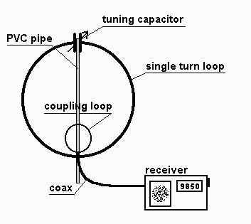
The small single turn magnetic loop (SSTML) antenna consists of a single winding inductor, about 3 feet (1 meter) in diameter, and a tuning capacitor. A second loop, which is one fifth of the diameter of the large loop,...
This document presents plans for a simple ground plane antenna that is effective in the FM band (88-108 MHz). It is constructed from a small plastic disk. The 6 x 6 loop antenna, designed by Graham Maynard, is highlighted...
This amplifier circuit is designed to enhance TV signals in the UHF range. It employs a low-noise transistor, providing an amplification of 10 to 15 dB within the frequency spectrum of 400 MHz to 850 MHz. It is crucial...
This circuit illustrates an active antenna suitable for AM, FM, and shortwave (SW) reception. On the shortwave band, this active antenna is equivalent to a 20 to 30-foot wire antenna. It is specifically designed for use with receivers that...
The elements diameter of the antenna may vary between 5...8mm and the dipole diameter may vary between 8...12mm (12mm recommended) without the need of changing anything to the length or spacing. All elements except the dipole are electrically connected...