
FM Radio Receiver Antenna Booster Circuit

The FM radio receiver antenna booster circuit is designed to enhance the reception capabilities of FM radio signals, particularly in areas with weak signal strength. The use of the BF324 TO92 style PNP transistor in a grounded-base configuration is crucial for optimizing the performance of the circuit. This configuration allows the transistor to operate with high input impedance while providing low output impedance, which is beneficial for signal amplification.
The circuit typically includes a few key components: the BF324 transistor, resistors for biasing, capacitors for coupling and decoupling, and an input/output connector for the antenna and radio respectively. The grounded-base configuration minimizes the impact of variations in the transistor's parameters, ensuring stable operation across a range of frequencies.
The input stage of the circuit connects the antenna to the base of the transistor through a coupling capacitor. This capacitor blocks any DC component from the antenna and allows only the AC signal (the FM radio signal) to pass through. The base resistor is employed to set the operating point of the transistor, ensuring that it remains in the active region for optimal amplification.
The output stage of the circuit connects the collector of the transistor to the radio receiver. An output capacitor is used to block any DC voltage from the collector while allowing the amplified AC signal to pass through to the radio. A load resistor may also be present to match the output impedance of the circuit with that of the radio receiver, maximizing power transfer.
In summary, this FM radio receiver antenna booster circuit effectively amplifies weak FM signals using a BF324 PNP transistor in a grounded-base configuration, making it a valuable addition for improving radio reception in challenging environments. Proper component selection and configuration are essential for achieving the desired performance characteristics.This inexpensive FM radio receiver antenna booster uses the BF324 TO92 style pnp transistor in a grounded-base configuration. The circuit may be used as a.. 🔗 External reference
Related Circuits
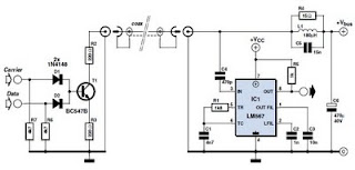
This circuit was designed to transmit commands over an LNB coaxial cable. An LNB (Low-Noise Block downconverter) is commonly used for satellite TV reception and is positioned at the focal point of a satellite dish. The circuit generates a...
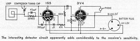
The Radio Hat was a portable radio integrated into a pith helmet, capable of receiving stations within a 20-mile (32 km) radius. It was launched in early 1949 for $7.95 under the name "Man-from-Mars Radio Hat." A successful publicity...

The amplifier is a quad amplifier circuit (amplifier with four inputs and four outputs) based on the TDA7381. This amplifier is designed for car audio systems, but it can also be utilized for other applications. The circuit has a...
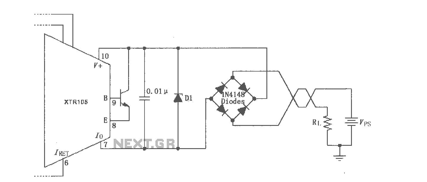
The XTR105 reverse voltage and over-voltage surge protection circuit is illustrated. A Zener diode rated at 36V can be utilized, with options including 1N4753A or 1N6286A. The maximum supply voltage (Vps) should be less than the minimum breakdown voltage...
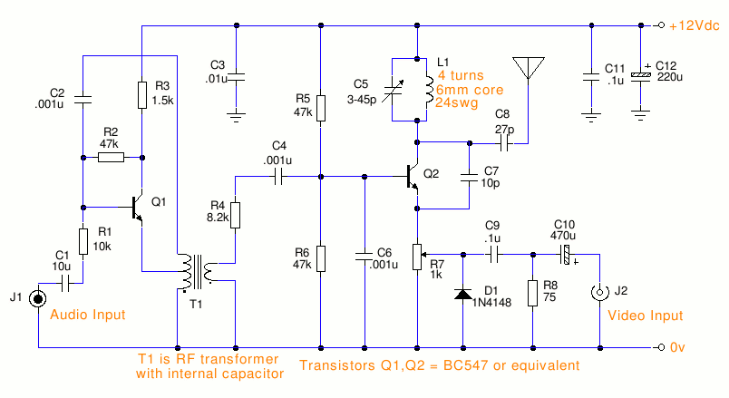
This is a small TV transmitter circuit that transmits in VHF, utilizing negative sound modulation and PAL video modulation. It is suitable for countries that use the B and G system. T1 refers to a type of transformer. The...

This project involves a 12V LED lamp circuit that is notably simple. The circuit comprises five resistors and fifteen super bright white 5mm LEDs, which are readily available at low prices. It is compatible with any type of 12-volt...