
96Mhz crystal oscillator
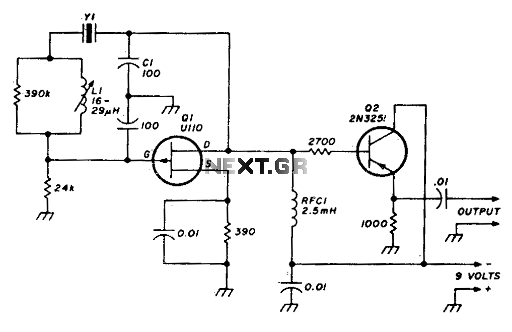
The described circuit operates as a variable crystal oscillator, which is crucial in applications requiring precise frequency control. The oscillator employs a fundamental frequency set by the crystal, which serves as a frequency reference. The inclusion of a capacitor and an inductor allows for fine-tuning of the output frequency through a technique known as frequency pulling.
In this configuration, the crystal is connected in series with the inductor and capacitor, forming a resonant circuit. The resonant frequency of this LC circuit can be adjusted by varying the capacitance or inductance, which alters the effective load on the crystal. When the frequency is adjusted slightly above or below the crystal's natural frequency, the circuit can pull the frequency in either direction, thus providing a range of output frequencies.
The stability of the oscillator is primarily determined by the quality factors of the inductor and capacitor, as well as the crystal itself. A high-quality crystal will exhibit low phase noise and minimal drift, making it suitable for applications such as RF transmission, where precision is paramount. Additionally, the choice of inductor and capacitor values must be carefully calculated to ensure that the circuit operates within the desired frequency range without compromising stability.
The output of the VXO can be further processed or amplified, depending on the specific application requirements. This flexibility makes the VXO a valuable component in various electronic systems, including communication devices, signal generators, and frequency synthesizers.Stable VXO using 6- or 8-MHz crystals uses a capacitor and an inductor to achieve frequency pulling on either side of series resonance. 🔗 External reference
Related Circuits
This crystal set has been designed to incorporate features from previous radio models. The #62 radio merges the single-piece design of the #48 set with the dual detector functionality of more recent models. It utilizes a dual honeycomb coil...

This circuit operates at or near series resonance. It has fair to poor circuit design with parasitics, touch to tune, and fair frequency stability. The circuit in question is designed to function at or near its series resonance frequency, which...
The objective is to test a Wien bridge oscillator and ensure its proper functionality. There is a study of relevant material, but some concepts remain unclear. The Wien bridge oscillator is a type of electronic oscillator that generates sine waves....

Edwin Henry Colpitts was a communications pioneer best known for his invention of the Colpitts oscillator. As research branch chief for Western Electric in the early 1900s, he and scientists under his direction achieved significant advances in the development...
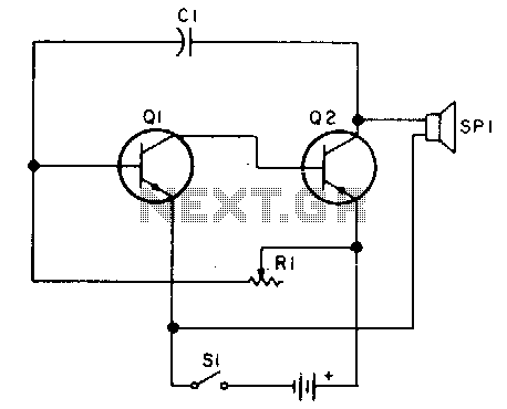
Oscillator, operates with 2 to 12 volts DC (optimal performance is achieved at 9 to 12 volts for maximum volume and clear keying). Additionally, R1 can be substituted with a 500K potentiometer, allowing the circuit to sweep across the...
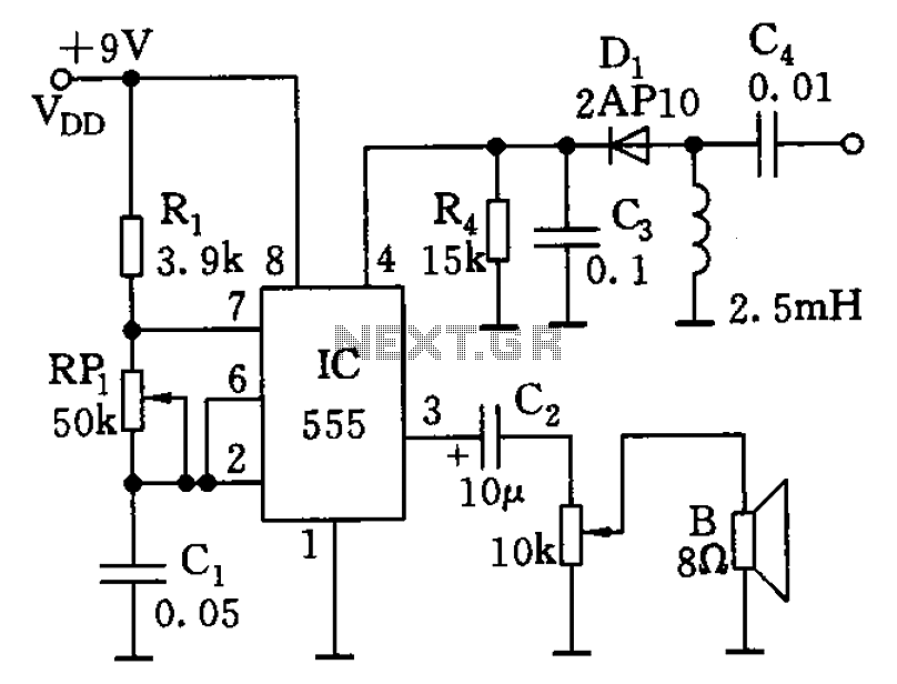
The circuit features a 555 timer along with resistors R1, RP1, and capacitor C1, functioning as a controllable audio oscillator. The frequency of the oscillator is determined by the formula f = 1.44 / ((R1 + 2 * RP1)...