
Wein bridge oscillator again

The Wien bridge oscillator is a type of electronic oscillator that generates sine waves. It utilizes a bridge circuit, which consists of resistors and capacitors arranged in a specific configuration to create a feedback loop. The oscillator operates based on the principle of positive and negative feedback, where the gain of the amplifier is adjusted to maintain oscillation.
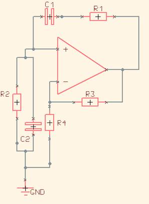
To construct a Wien bridge oscillator, the following components are typically required: an operational amplifier (op-amp), four resistors (R1, R2, R3, R4), and two capacitors (C1 and C2). The resistors R1 and R2 are typically equal, and capacitors C1 and C2 are also equal, which establishes the frequency of oscillation. The frequency (f) of the output sine wave can be calculated using the formula:
f = 1 / (2πRC)
where R is the resistance value and C is the capacitance value used in the circuit.
The circuit configuration involves connecting the resistors and capacitors in a bridge arrangement. The output of the op-amp is connected to the junction of R1 and R2, while the feedback loop is established through R3 and R4. The gain of the op-amp is adjusted using a variable resistor or a thermistor, which helps stabilize the amplitude of the oscillation.
In operation, the Wien bridge oscillator begins to oscillate when powered on, provided that the gain of the amplifier is set correctly. If the gain is too high, the output will clip, leading to distortion. Conversely, if the gain is too low, oscillations may cease. Therefore, a balance must be achieved for the oscillator to function effectively.
To troubleshoot any issues, it is essential to verify the values of the resistors and capacitors, ensure proper connections, and check the power supply voltage. Additionally, an oscilloscope can be used to visualize the output waveform, aiding in diagnosing any problems with the circuit's performance.Hi I am testing wein bridge oscillator and I looking to make it work. I have study the page below, but there are some concept i do not understand.. 🔗 External reference
Related Circuits
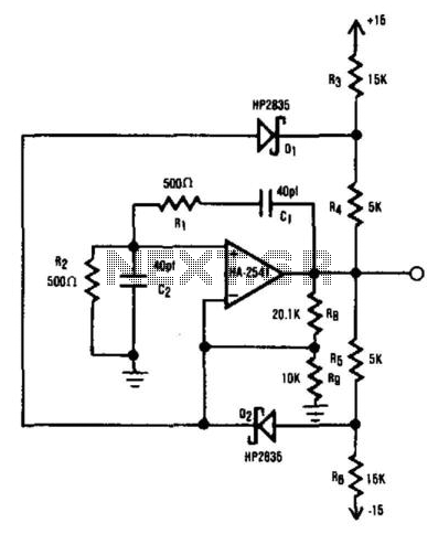
The HA2541 is ideal for use as the core component of an oscillator. Despite the basic diode limiting provided by R3 through R7 and D1 and D2, a high-quality sine wave at 40 MHz can be easily achieved, with...
In the Hartley circuit, the amplified energy from the plate circuit is fed back to the grid circuit through fluctuating magnetic fields. Both circuits utilize magnetic feedback. The Hartley circuit employs a single coil, with part of it situated...
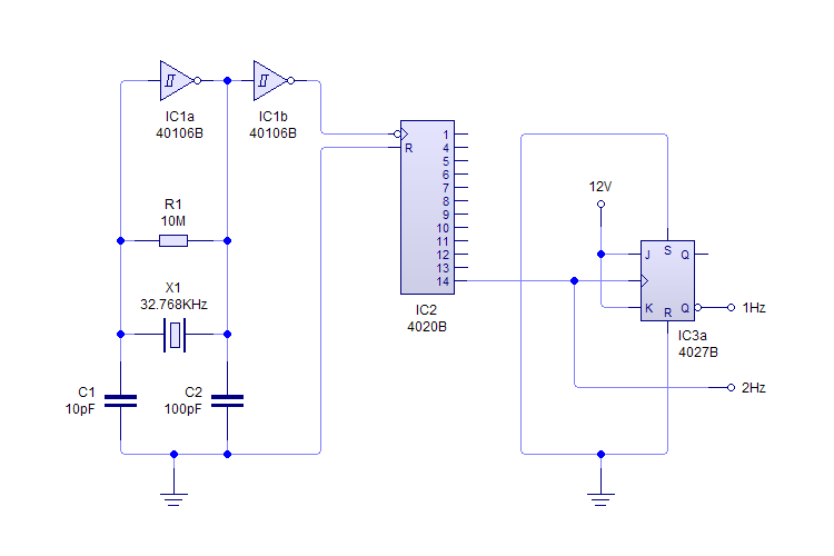
This plugin utilizes a quartz oscillator featuring a crystal (X1) to produce a 32,768 Hz (32,768 = 2^15) output. This frequency is fed into a 4020 14-Stage Ripple Counter, which divides the signal by 2^14, resulting in a 2...
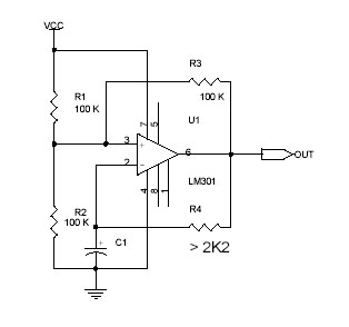
This circuit utilizes the Op-Amp LM301 to generate a simple square wave. The LM301 operates with a power supply range of 3 V to 36 V and can handle a maximum frequency of 325 kHz. The oscillation frequency is...
One of the simplest sine wave oscillators is the Wien Bridge Oscillator. Any circuit requires two conditions to oscillate. Tracing the path from the input, through the feedback network, and back to the input, there must be an overall...
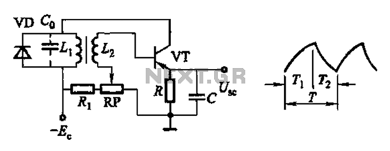
Common non-sinusoidal oscillator circuit, waveform and frequency formula - pulse wave oscillator - single-junction transistor blocking oscillator. The common non-sinusoidal oscillator circuit described is a pulse wave oscillator that utilizes a single-junction transistor in a blocking configuration. This type of...