
99 mV to 999 mV meter schematic

The circuit described is a voltage measurement system designed for applications such as dietary monitoring, where precise voltage readings are essential. The system can measure a voltage range from -99 mV to 999 mV, making it suitable for various low-voltage applications.
The main components of the circuit include two integrated circuits (ICs), the CA 3161 and CA 3162. The CA 3162 (IC1) functions as an analog-to-digital converter (ADC), converting the input analog voltage signal into a digital representation. This digital signal is multiplexed, allowing control over multiple display outputs (T1 to T3). The resulting Binary-Coded Decimal (BCD) output from IC1 is fed into the CA 3161 (IC2), which serves as a BCD to 7-segment display driver. This configuration allows the digital representation of the measured voltage to be displayed on common anode 7-segment LED displays (LD1 to LD3).
Pin 6 of IC1 is a versatile control pin that influences the sampling frequency of the circuit. When this pin is grounded or left open, the circuit operates at a sampling frequency of 4 Hz. If a voltage of 1.2 V is applied to pin 6, the HOLD function is activated, freezing the displayed value. At a voltage of 5 V on pin 6, the sampling frequency increases to 96 Hz, allowing for more rapid measurements.
Calibration of the meter is achieved through two potentiometers, P1 and P2. P1, a 10 kΩ trimming potentiometer, is used to set the display to indicate "000" when no voltage is applied. A known reference voltage between 0 to 1 V is then applied to the HI input while LO is grounded. Next, P2, a 5 kΩ trimming potentiometer, is adjusted to ensure that the display accurately reflects the input voltage in millivolts.
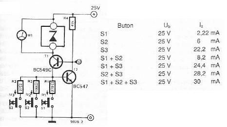
To extend the measurement range, voltage dividers can be utilized. The circuit also includes resistors R1 to R3, each valued at 220 Ω, which are likely used for current limiting or biasing purposes. The capacitor C1, rated at 270 nF, is likely employed for filtering or stability in the circuit. The transistors T1 to T3 (636 BC) are used for switching the multiplexed signals to the display segments.
Overall, this circuit design provides a robust solution for precise voltage measurement, suitable for various applications that require accurate monitoring of low voltage levels.This circuit can for example be incorporated into a diet to pressure warning. The meter can measure voltages from -99 mV to 999 mV. The circuit uses two ICs, the CA 3161 and CA 3162. IC1 converts the analog signal into a digital signal. IC1 is also the multiplexed signal to T1-T3 can be controlled. The BCD code is then fed to IC1 IC2, a BCD/7-segments converter. Then the signal is fed to the displays. Pin 6 of IC1 (hold) can be used for a number of things. When pin 6 is grounded or open, the 4 Hz sampling frequency. When pin 6 is at 1.2 V, then enter the HOLD function is activated. The output will remain unchanged, so the display is put down. If pin 6 is at 5 V, the sampling frequency 96 Hz. Adjusting the meter is through the HI and LO inputs to GND. P1 is then adjusted so that the display "000" indicates. Then a known voltage from 0 to 1 V is connected to HI and LO (LO to GND). The display then P2 so cut that regulates the voltage in mV is indicated. With voltage dividers, the range can be increased. The points of the displays can be used by dp 1, 2 and / or 3 to GND. R1-R3 = 220 ? P1 = 10 kOhm 10 or 15-turn trimming potentiometer P2 = 5 kOhm 10 or 15-turn trimming potentiometer C1 = 270 nF T1-T3 = 636 BC IC1 = CA 3162 IC2 = CA 3161 LD1-LD3 = 7-segment LED display common anode 🔗 External reference
Related Circuits

A unified thermometric controller that can be programmed with simple scripts, integrating the "classic" thermometer/controller pair. You can build a variety of simple machines with the same hardware and a different script: a charting thermometer, a vending machine that...
The electronic scheme provided can be used to design a Zener diode tester utilizing a few electronic components. This Zener tester, in conjunction with a multimeter, allows for the precise measurement of the threshold voltage of a Zener diode....
The CA3189 integrated circuit (IC) incorporates a symmetrical limiter, a phase demodulator, an audio amplifier, and a logarithmic detector-amplifier. The logarithmic detector-amplifier is particularly noteworthy for enhancing the logarithmic signal meter of shortwave receivers, thereby improving signal reading accuracy....
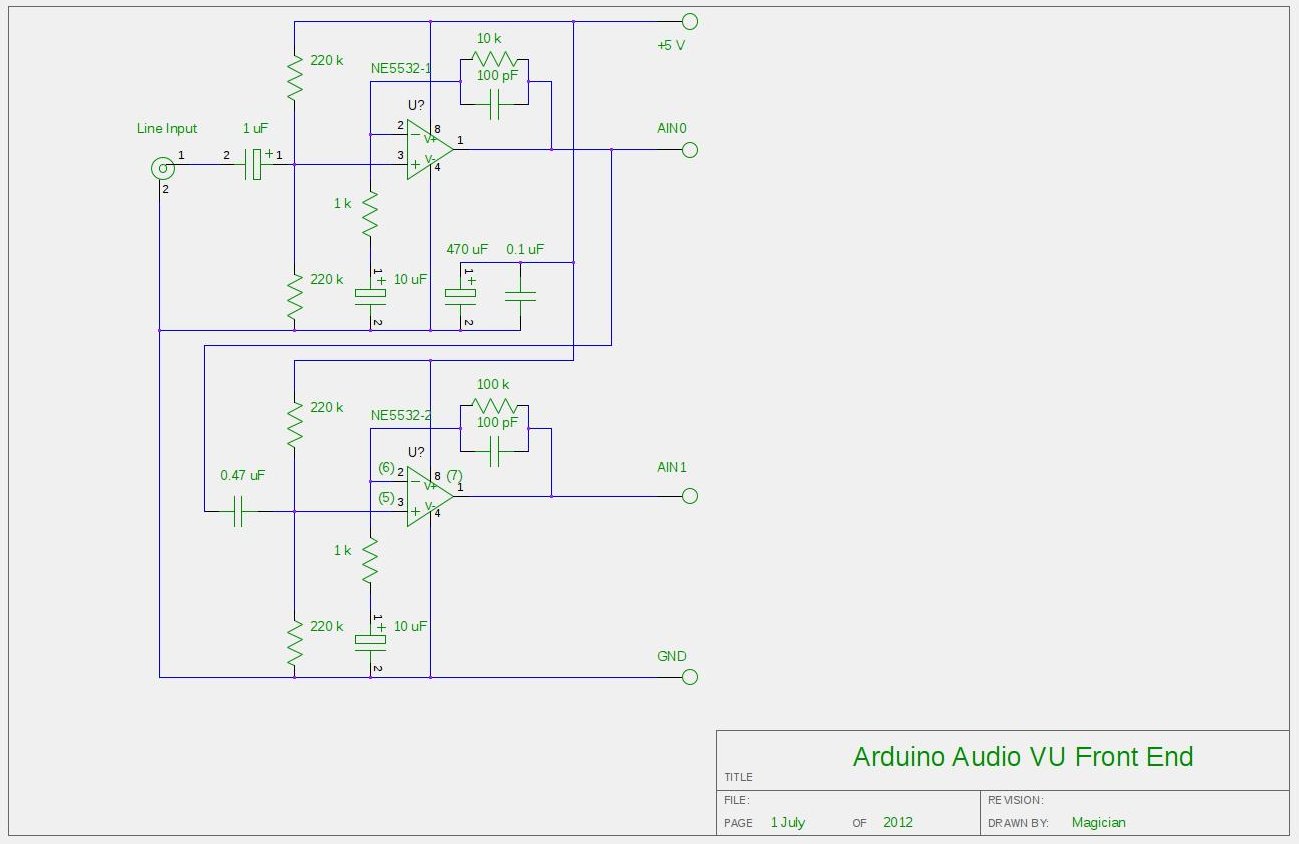
After experimenting with a stereo version of the VU meter described in a previous blog post, a studio-grade VU meter is now being presented. This meter features 24 steps, spaced equally every 3 dB, and covers a wide dynamic...
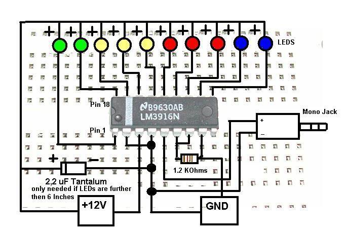
This is a concise guide for constructing a stereo VU meter utilizing the LM3915/LM3916 integrated circuits. The LM3916 is designed to convert analog voltage levels into visual representations through the activation of 10 LEDs, LCDs, or vacuum fluorescent displays,...
This watt-meter circuit has a measurement range of up to 1 kW. It can provide complete (X)(Y) functionality while utilizing only one transistor. The circuit is designed for operation with 117 Vac ± 50 Vac. Modifications can be made...